l Configuration file of SwitchE
#
sysname SwitchE
#
router id 5.5.5.5
#
vlan batch 40
#
interface Vlanif40
ip address 172.16.1.2 255.255.255.0
#
interface XGigabitEthernet0/0/1
port trunk allow-pass vlan 40
#
ospf 1
area 0.0.0.1
network 172.16.1.0 0.0.0.255
nssa
#
return
4.14.4 Example for Configuring DR Election of an OSPF Process
Networking Requirements
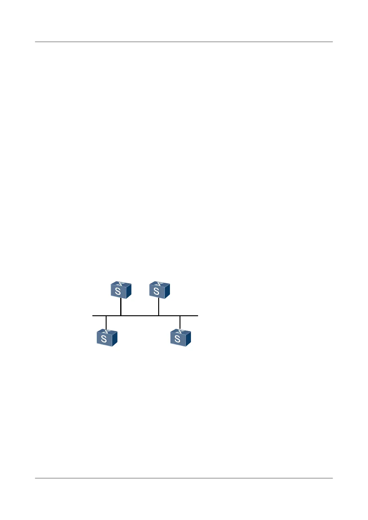
As shown in Figure 4-8, Switch A has the highest priority of 100 in the network and is selected
as DR. Switch C has the second highest priority, and is selected as BDR. The priority of Switch
B is 0, so Switch B cannot be selected as DR. The priority of Switch D is not configured and its
default value is 1.
Figure 4-8 Networking diagram for configuring DR election of an OSPF process
Switch A Switch B
Switch C Switch D
XGE 0/0/1
XGE 0/0/1
XGE 0/0/1
XGE 0/0/1
Switch
Interface VLANIF IP address
SwitchA XGE 0/0/1 VLANIF 10 192.168.1.1/24
SwitchB XGE 0/0/1 VLANIF 10 192.168.1.2/24
SwitchC XGE 0/0/1 VLANIF 10 192.168.1.3/24
SwitchD XGE 0/0/1 VLANIF 10 192.168.1.4/24
Configuration Roadmap
The configuration roadmap is as follows:
S6700 Series Ethernet Switches
Configuration Guide - IP Routing 4 OSPF Configuration
Issue 01 (2012-03-15) Huawei Proprietary and Confidential
Copyright © Huawei Technologies Co., Ltd.
151

 Loading...