S6720-EI Power Supply Configuration
An S6720-EI switch can have one or two power modules installed.
When a switch has two power modules installed, the two power modules work in 1+1 redundancy
mode. AC and DC power modules can be used together in the same switch.
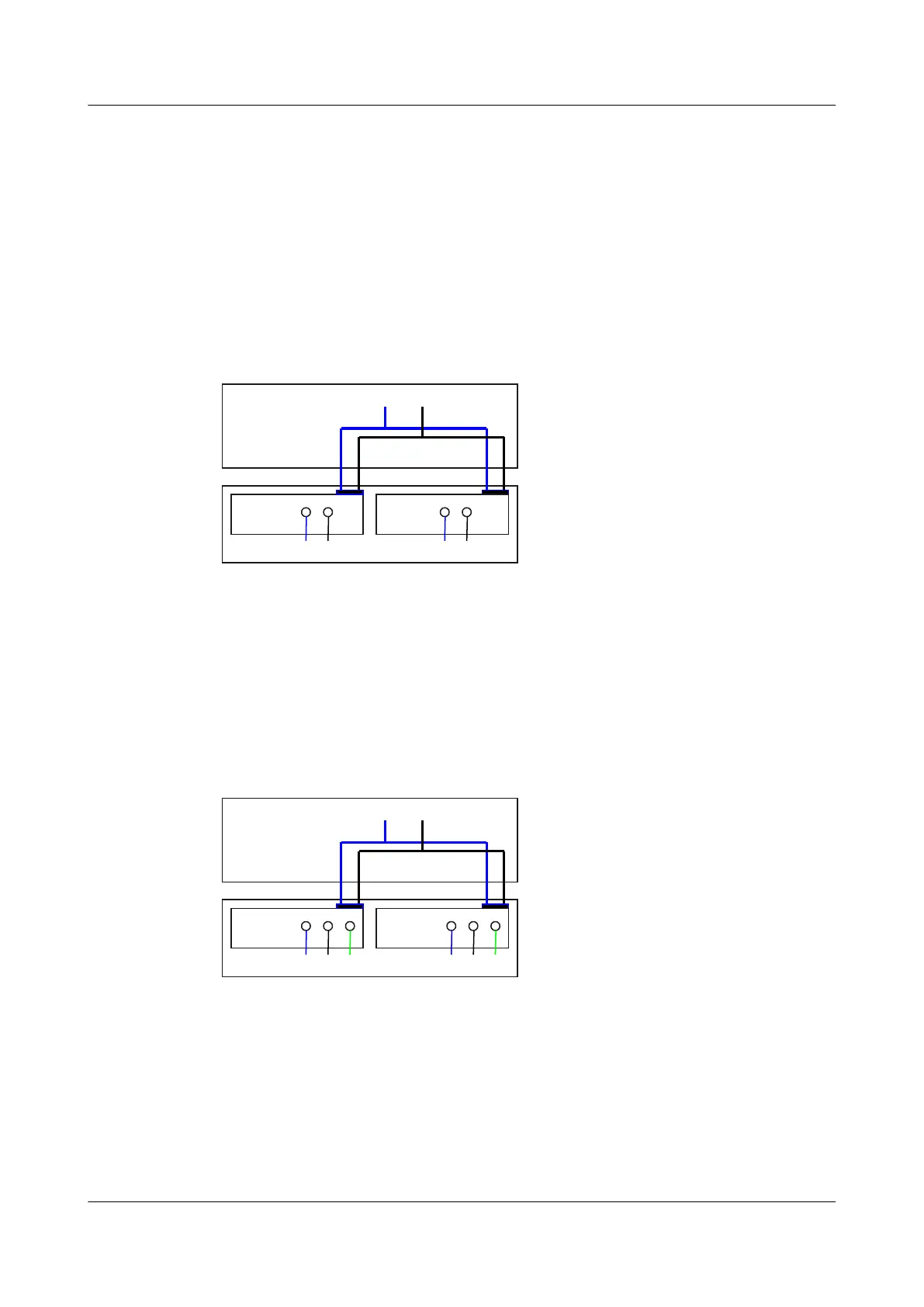
Figure 2-11 shows the power supply connections of dual DC power modules. After DC power
is transmitted to the PWR module, the PWR module provides 12 V output voltage, and the
motherboard provides power for the entire device.
Figure 2-11 Power supply connections of dual DC power modules
PWR2
NEG RTN
Motherboard
GND12V
PWR1
NEG RTN
NEG: Negative cable
RTN: Positive cable GND: 12 V reference ground
Figure 2-12 shows the power supply connections of dual non-PoE AC power modules. After
AC power is transmitted to the PWR module, the PWR module provides 12 V output voltage,
and the motherboard provides power for the entire device.
Figure 2-12 Power supply connections of dual non-PoE AC power modules
PWR2
L N
Motherboard
GND12V
PGND
PWR1
L N PGND
L: Live wire
N: Neutral wire PGND: Protective ground wire GND: 12 V reference ground
2.5.6 Heat Dissipation
Table 2-21 lists the heat dissipation method of the S6720-EI series switches.
S6700 Series Ethernet Switches
Hardware Description
2 Chassis
Issue 12 (2015-07-31) Huawei Proprietary and Confidential
Copyright © Huawei Technologies Co., Ltd.
38

 Loading...