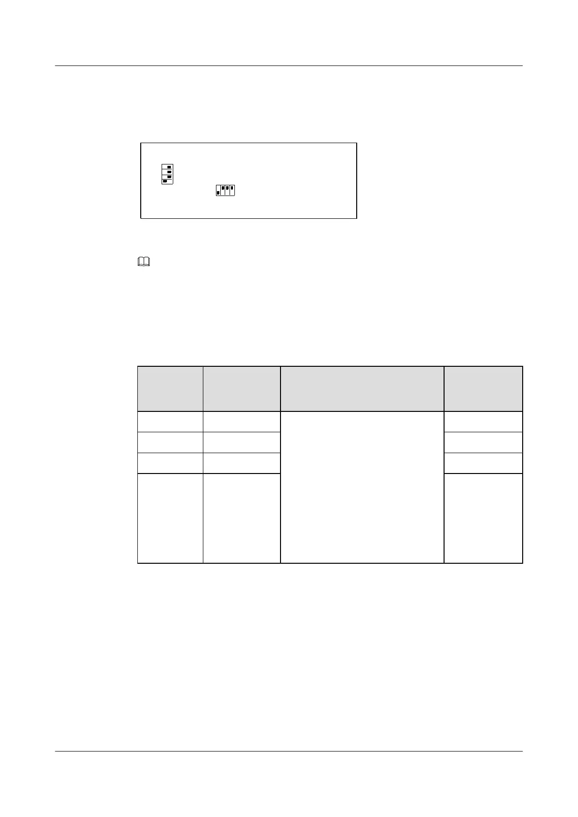
The H612FCBA monitoring board of the fan tray provides two sets of DIP switches: SW1 and
SW2. Figure 9-4 shows the layout of SW1 and SW2.
Figure 9-4 Layout of SW1 and SW2 (default settings)
H511FDMB
SW1
SW2
1234
ON OFF
1
2
3
4
ON
OFF
NOTE
The PCB board of the H612FCBA board is H511FDMB.
DIP Switches of SW1
Table 9-15 describes the indications and default settings of the DIP switches of SW1.
Table 9-15 DIP switches of SW1
DIP Switch
Connector
Correspondin
g to the Fan
Indication Default
Setting
SW1-1 J1 SW1-1 is a switch to shield the signals
of the fault alarms generated by fan
trays.
In the case of connectors that are not
connected to fan trays, set SW1 to
shield the signals of alarms before the
fan monitoring board works.
l ON: The connector is idle and is
not connected to a fan.
l OFF: The connector is connected
to a fan.
ON
SW1-2 J2 OFF
SW1-3 J3 OFF
SW1-4 J4 OFF
DIP Switches of SW2
Table 9-16 describes the indications and default settings of the DIP switches of SW2.
UA5000 Universal Access Unit
Environment Monitoring 9 Fan Tray Monitoring Solution
Issue 01 (2012-08-17) Huawei Proprietary and Confidential
Copyright © Huawei Technologies Co., Ltd.
159
 Loading...