Installation Instructions
Hustler 6-BTV Trap Vertical
ASSEMBLY
1. Check the package contents against the parts list on page 2.
2. WARNING. Installation of this product near power lines is dangerous. For your safety,
read the enclosed warnings and follow the installation directions.
3. Prepare split lead on coax in accordance with figures 2 and 3. RG-8/U coax is
recommended. (See decoupling information, page 12).
4. Install lugs on coax as shown in figure 4 and weatherproof with electrical tape.
5. Install coax feedline and radials (if needed) as shown in figure 7. Coax length is not
critical.
6. After making all connections it is recommended you spray the bracket assembly with a
heavy protective coating such as Krylon clear spray coating.
7. Assemble all 1-1/4 in. stainless steel clamps using the 1/4 in.-20 x 3/4 in. screws and 1/4-20
square nuts.
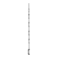
8. Attach the 10-meter trap to the 72 in. tube using one of the clamp assemblies. Set
dimension “A” as indicated in the table in figures 5 and 6.
9. Assemble one of the 20 in. tubes on top of the 10-meter trap using a clamp assembly. Place
the 15-meter trap on top of the 20 in. tube and set dimension “B” (see table figures 5 and
6). Repeat this step with another 20 in. tube and install the 20-meter trap. Set dimension
“C”.
10. Put the 24 in. tube above the 20-meter trap. Place the 30-meter trap on it, using clamp
assemblies. Set dimension “D” (figures 5 and 6).
11. There is no trap for 40 meters. The 40-meter section consists of a 36 in. tube with a
threaded stud on the upper end. Install the 40-meter tube on the top of the 30-meter trap.
Set dimension “E” (figures 5 and 6).
12. Screw on the 75/80-meter resonator at the top of the 40-meter tube and adjust the tip rod in
accordance with figure 8.
NOTE: The Hustler RM-75S and RM-80S resonators are the same. Tip rod length is the
only difference.
13. Place the antenna on the bracket assembly and set dimension “A”, using the last clamp
assembly.