Power supply control board settings
2 Field Service Bulletin
HPR CONTROL BOARD REPLACEMENT
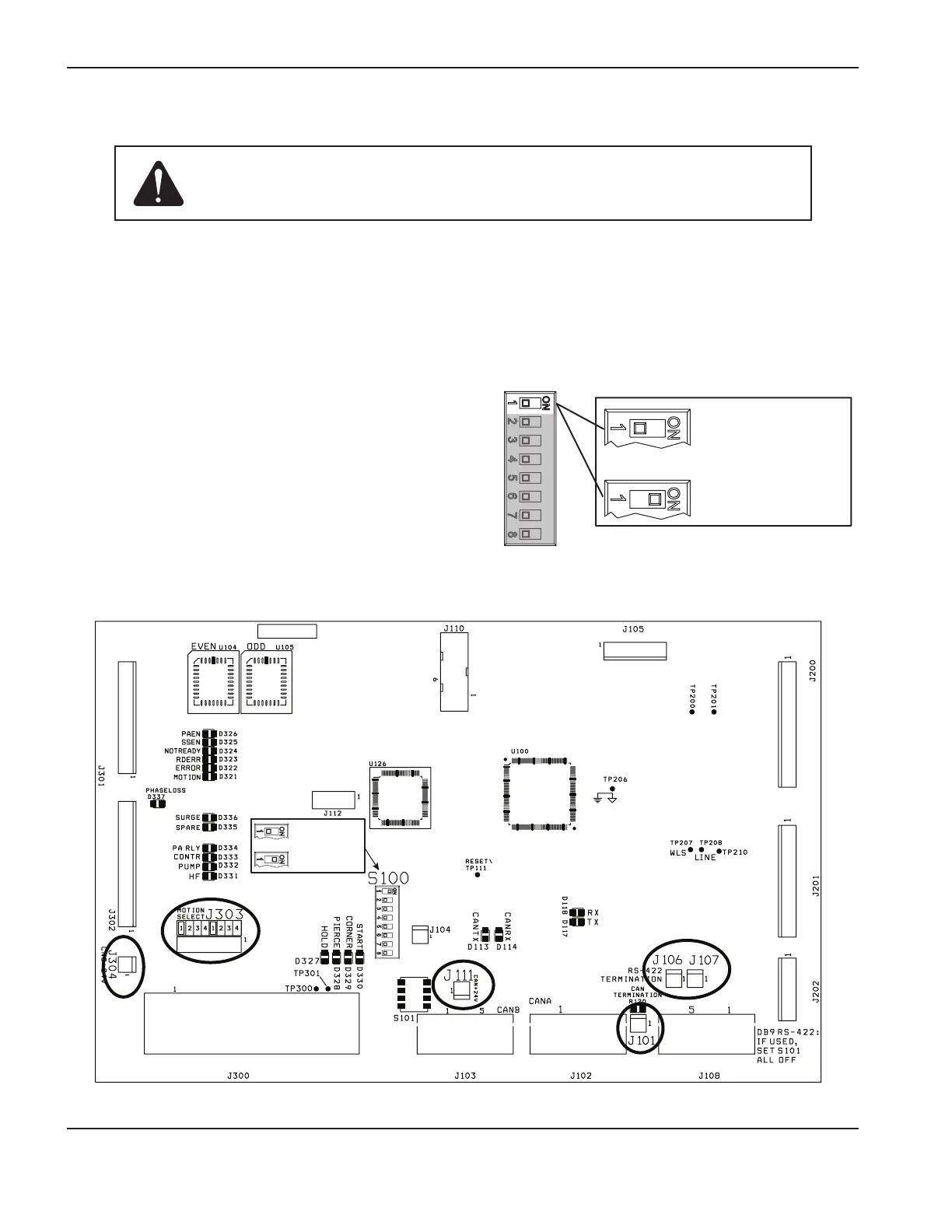
DIP switch location and settings
The dip switches on the new board must match the dip
switches on the old board.
Switch number 1 determines if the board is being used in
an HPR130 (OFF position) or an HPR260 (ON position).
Switches 2 and 3 are used when the plasma system has
more than one power supply in series (also referred to as
multi-drop systems). Switches 4 through 8 must be in the
OFF position. See the wiring diagrams in your instruction
manual for more information on multi-drop systems).
= HPR130
= HPR260
Caution: Do not discard the old control board until the installation is complete.
All jumpers and dip switches on the new control board must match the
settings on the old control board for the system to work correctly.
Jumpers
The jumpers on the new control board must match the jumpers present on the old control board. Configure the jumpers
on the new control board to match the jumpers on the old control board in the corresponding locations. See the figure
below for jumper locations.
041993
HPR130XD and HPR260XD power supply control board
= HPR130
= HPR260

 Loading...


