Uninstallation
1
2
3
U
n
pl
ug
Rotate
1
2
3
4
1 2 3 4 5 6 7 8 9 10 11 12 1 3 14 15 16
COLUMN
ROW
Pos iton:
Mod el:
She et of
Cos tumer I nforma tion:
Mic roinve rter In stall ation M ap
N
w
S
E
NW NE
SW SE
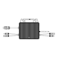
3. Push the buckle open with the tool as shown, Rotate the latch as shown, unplug the male and female
ends to unlock the cables.
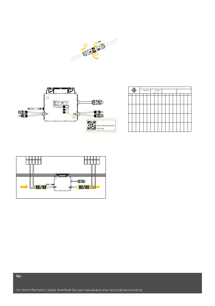
2.4 Installation Map
1. Peel the removable serial number label from each microinverter.
2. Affix the serial number label to the respective lacation on the installation map.
1. Mount the PV modules above the micro inverter .
2. Connect the PV modules’ DC cables to the DC input side of the micro inverter.
2.5 PV Connection
3.Commissioning
Please check if
1. The inverter and mounting bracket have been correctly installed. 2.The inverter’s exposed metal
surface has a ground connection. 3.The resistance between PV arrays and ground is greater than
1Mohm. 4.The grid voltage at the point of connection of the inverter is within the permitted range.
5.The AC circuit breaker must be correctly rater and wired.
Startup
1. Turn on the AC breaker for the branch circuit.
2. Turn on the main AC breaker for the house. Your system will start to generate power in about two
minutes.
www.hypontech.com
+86 400 6339 990
Service Contact: service@hypon.com
www.hypon.com
www.hypon.com
Address: No.588 Wutaishan Road, SND, Suzhou , China
/ E-mail:
info@hypon.com
/ Web:
2
INMETRO
Micro inver ter Model: HMS-800W-C
HMS -800 W-C
HMS -800 W-C
HMS -800 W-C
HMS-800W-C
 Loading...