Quick Installation Guide
HPS-1500 / HPS-2000 / HPS-3000 / HPS-3680 / HPS-4000 / HPS-5000 / HPS-6000 / HPS-6500
HPS-1500D / HPS-2000D / HPS-3000D / HPS-3680D / HPS-4000D / HPS-5000D / HPS-6000D / HPS-6500D
H838-00001-01
EN
3.
Installing
Installation Requirements
1. Please install the inverter(s) in places that can avoid
inadvertent contact.
2. Please install the inverter on solid/smooth surfaces.
3. The inverter(s) should not be installed near inflammable or
explosive objects.
Installing the PE Cable
A second PE terminal is equipped at the bottom of the inverter.
Ensure the PE terminal is reliably grounded and the grounding resistance is
less than 10 Ohm.
3.2
Object
Description
1
Housing
2
M5 terminal lug with protective conductor
3
M5×13 pan head screw
Tighten it firmly into the housing (T25 screwdriver, torque: 2.5Nm).
NOTICE
Proper grounding connection of the second PE terminal and the AC terminal is mandatory. NOT properly connecting
both PE will void all product warranty.
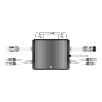
Packing List
Inverter
Mounting
Bracket
Mounting
Accessories
DC Plugs
(Sealed)
AC Connector
Wi-Fi stick
(optional)
Documents
1 1 1 1* 1 1 1
*2 pairs for HPS-3680/4000/5000/6000/6500 and HPS-3680D/4000D/5000D/6000D/6500D
2.
Direct
Sunlight
Rain
Exposure
Snow
Lay up
AVOID
No Item
Type
Specifications
1
PE cable
Single-core outdoor copper cable
• Conductor cross-section: ≥ 4mm²
2 AC Output
cable
Outdoor copper cable
• HPS-1.5~3kW - cross-section: 2.5-6 mm²
• HPS-3.68~6.5kW - cross-section: 4-6 mm²
• Cable outer diameter: 9-14 mm
3 DC Input
cable
Standard outdoor PV cable,
PV1-F Model recommended
• Conductor cross-section: 2.5-6 mm²
• Cable outer diameter: 4.5-7.8 mm
4 Meter
Two-core outdoor shielded
twisted pair cable
• Conductor cross-section: 0.14-1.5 mm²
• Cable outer diameter: approx. 9 mm
5 DRED
CAT-5E, outdoor shielded cable
Standard for EIA/TIA 568B
• Cable outer diameter: approx. 9 mm
• cable maximum length 1000m
Cable Specifications
Mounting
3.1.1 Use the mounting bracket as a template and drill holes of 10mm diameter and 70mm depth
3.1.2 Fix the mounting bracket with the screws and expansion bolts packed in mounting accessories
3.1.3 Attach the inverter to the mounting bracket
3.1.4 Check both sides of heat sink and ensure the inverter is stably attached
3.1.5 Use M5 screws (with T25 screwdriver, torque: 2.5Nm) to attach the heat sink fins to the mounting bracket
3.1.6 It is recommended to attach an anti-theft lock to the inverter
3.1
1
2
3
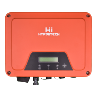
1. LCD&LED or LED
2. DC switch (optional)
3. PV Terminal (s)
4. Wi-Fi/GPRS Stick(optional)
5. Cable gland for Meter/DRM
6. AC Terminal
7. Second PE Terminal
Product Overview
1.
W
H
D
1
2 3 4 5 6 7
10mm(2Χ)
Deep 70mm
160mm
Step 1
Step 2 Step 3
Step 4 Step 5 Step 6
160mm
Standby holes
Dimension:W×H×D=395 x 328 x 154mm