3.2
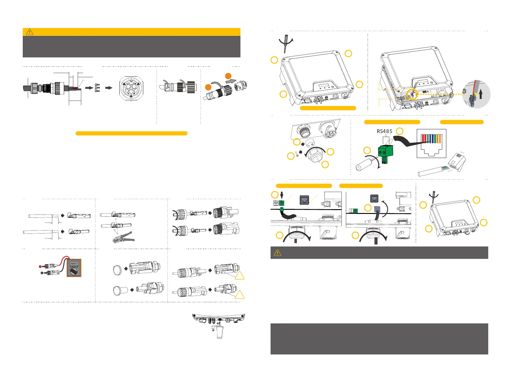
AC Wire Assembly and Connection
Danger to Life due to High Voltages in the Inverter
Before connecting any electrical wires and components, please ensure the DC switch & AC circuit breaker are switched
OFF and cannot be reactivated.
DANGER
DC Wire Assembly and Connection
Meeting the following requirements is mandatory. All warranty rights will otherwise be invalid.
3.3.1 Maximum open voltage of each string is less than 600V.
3.3.2 Maximum short circuit current of each PV input is less than inverter allowable limit.
3.3.3 The string is well insulated to ground in all cases.
3.3.4 Make sure that the DC connectors have the correct polarity.
3.3.5 If the PV connectors are not assembled properly and locked into place, arc or overheat may be induced.
3.3
Wi-Fi Connection (Optional)
The Wi-Fi stick is included in the scope of delivery as an option.
3.4.1 Tighten the Wi-Fi stick into the Wi-Fi connection port by hand. Make sure the Wi-Fi stick is securely
connected.
3.4.2 For the connection and configuration of the Wi-Fi stick please refer to <Wi-Fi stick User manual> .
3.4
Note: Please insure that the connector has been correctly installed!
Step 1
Step 2 Step 3
Step 4 Step 5 Step 6
Strip off the insulation
7mm
Positive terminal
Negative terminal
Assemble the cable ends
Positive terminal
Negative terminal
Crimp pliers to
cable ends
Assemble the connectors
2.6-2.9 N·m
Positive
Negative
Please check if the cables are securely
installed by pulling outwards
Check the polarities of the PV strings
Check the open-circuit voltage is less
than inverter input limit 600V
Remove the waterproof caps from
PV terminals
If there is an unused terminal,
please seal it with the cap
Insert the connectors into the terminal till you
hear an audible click.
7mm
click
click
Insert the conductor into a suitable
ferrule acc. to DIN 46228-4 and crimp
Insert the crimped conductors L, N and PE
into corresponding terminals and tighten the
screws (torque 1.4N·m)
Assemble the locking cap,
threaded sleeve and swivel
nut together
Screw the AC connector
firmly into the socket
Step 1
Step 2 Step 3
Please check if
1. The inverter and mounting bracket have been correctly installed. 2. The inverter’s exposed metal surface has a ground
connection. 3. The resistance between PV arrays and ground is greater than 1Mohm. 4. For any unused DC terminals,
there are DC connectors inserted to the terminal and sealed with waterproof caps. 5. The grid voltage at the point of
connection of the inverter is within the permitted range. 6. The AC circuit breaker must be correctly rated and wired. 7.
The cable communication connectors have been correctly wired and tightened.
Startup
Switch on the DC switch after finishing the above checks, then switch on the AC circuit breaker. When there is sufficient DC
power applied and the grid conditions are met, the inverter will start to operate automatically.
Commissioning
4.
Warranty card will be shipped with inverter. Download of current warranty conditions is available at https://www.hypontech.com
Suzhou Hypontech Co.,Ltd / Tel.: +86 0512-80712199 / Fax: +86 0512-80712382 / Web: www.hypontech.com
Address: No.588 Wutaishan Road, SND, Suzhou, China
For more information, please download the user manual and other technical documents at
https://www.hypontech.com/downloads.html
Smart Meter and DRED Connection
Smart meter and DRED connection
as following steps.
3.5
NOTICE
For AS/NZS 4777, DRM0, DRM5, DRM6, DRM7, DRM8 are supported.
Make sure the cover and the communication cable gland has been mounted properly and adequately
DREDDREDMETER
Pin1:DRM1/5
Pin2:DRM2/6
Pin3:DRM3/7
Pin4:DRM4/8
Pin5:RefGen
Pin6:Com/DRM0
Pin7:N/A
Pin8:N/A
1
2
3
4
5
6
7
8
Rj45 Plug
1 8
Rj45 Plug
B
A
Step 1
Step 2
Step 3
Step 4
Step 5
Step 6
Use a screwdriver (Tx25, torque:2.5 N·m) to
loosen the screws of the cover following the
indicated sequence (1~4)
1
2
3
4
Please leave the screws on the holes
Carefully lift the cover for a vertical distance of approx. 80mm and
disconnect from power board
Approx.
80mm
1
2
3
4
Unscrew
the nut
Take the
sealing out
Remove one of the filler-plug
and keep the remaining in its
slot to prevent moisture from
enter
Route
the cable
Screwdriver Type: Blade 0.4 x 2.5
1
2
or
For smart meter connection DRED terminal connection
1
2
1
2
Tighten the screws on the cover following
the indicated sequence (1~4).
Firmly secure cable gland by using a torque
of 2.5 to 3N·m to tighten the swivel nut
(Tx25, torque:2.5 N·m)
1
2
3
4
φ9-14 mm
Approx. 45 mm
Approx. 10 mm
For “L” and “N”
For “PE”
Approx. 50mm
HPS1500-3000 2.5....6mm²
HPS3680-5000 4....6mm²
PE
L
N
Smart meter communication assembly DRED cable assembly
or
1
2
 Loading...