3-3
STARTUP AND COMMISSIONING
SFC COMBI BOILERS SFC-99, SFC-125
To verify the proper operation of the gas valve in the eld, the following procedure
can be carried out by a qualied technician (see diagrams on this page).
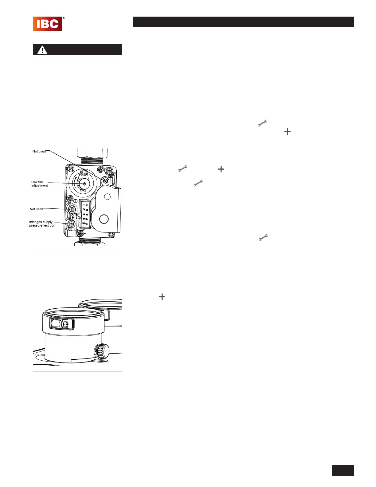
1. Turn off the unit’s manual gas valve. With a Torx 15 screwdriver, open
the inlet gas supply pressure test port by turning its screw 1 full turn
counterclockwise. Attach a manometer to the pressure test port. Turn on
gas to the appliance. Static manometer reading should be ideally 7” w.c.,
for natural gas and 11” w.c. for propane. Minimum and maximum static
pressure must be between 5” and 14” w.c. Monitor pressure throughout the
commissioning procedure. Pressure may droop up to 1” at high re.
2. Allow the unit to ignite / run against a large load, to maintain high re. To set
the high-re manually, press and hold the Service icon for two seconds.
Then while holding the Service icon press the Plus button twice. “H” will
show in the service display as the unit enters high re.
NOTE: Allow the unit to operate at high re for 3 minutes to stabilize.
(The unit operates in manual mode for 10 minutes then switches back
to the normal operating mode. To extend manual mode operation, press
the Service and Plus together twice while the unit is operating
in manual mode to reset the timer for 10 more minutes.) Do not make
adjustments if the Service display shows an “h”.
3. Clock the natural gas meter to conrm full maximum rating plate input. With
a combustion analyzer probe in the ue gas test port, check the measured
results against Table 12 - High Fire. If the results are outside the permitted
range, check the inlet pressure, and conrm that the correct orice and
venturi are installed. For areas of lower caloric value natural gas, install the
alternative orice listed on page 3-4.
4. Switch the unit to low re by pressing the Service button and Minus
-
buttons at the same time. The unit will drop to low re. “L” will show on the
service display. Compare the readings with Table 12 - Low Fire. If adjustment
is necessary, remove the low re adjustment cap to reveal a Torx head screw.
Make minimal adjustments, typically less than 1/8th of a turn at a time. Turn
the screw clockwise to increase CO
2
and counter-clockwise to reduce CO
2
.
If the target cannot be met, even after a full turn, contact the factory. When
nished, replace the low re cap, and leave the manual mode by pressing
Plus AND Minus - simultaneously.
5. Switch off the unit by pressing the space above the dot for two seconds. Turn
off the gas at the unit’s manual gas valve. Remove the ue gas analyzer
from the test port and reinstall the test port cap. Remove the gas pressure
manometer from the gas valve and fully close the test port. Turn on the gas
at the appliance’s gas shut off valve. Ensure that there are no gas leaks and
reinstall the front cover. Turn on the unit by pressing the space above the dot
for two seconds.
Figure 40 Gas Valve Adjust
Figure 41: Flue gas test port plug
WARNING
Check the rating plate of the
unit to ensure it is congured
for the fuel you are using. If
the fuel is incorrect for the
appliance, a conversion kit
must be ordered from IBC
and the gas valve adjusted
accordingly.
Failure to perform the
required fuel conversion can
result in an immediate hazard.
 Loading...


