6-5
DIAGRAMS
SFC COMBI BOILERS SFC-99, SFC-125
6.2 WIRING DIAGRAMS
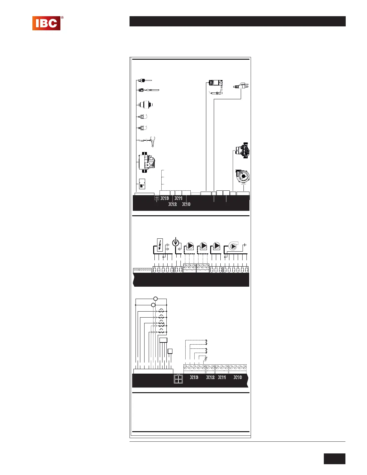
Diagram 6.2-1: Pictorial wiring diagram
Remarks:
Number:
Material:
Projectnr:
Author:
Date:
Name:
Projection:
Size:Units:
Scale:
17/02/15 HBs16-121
Zie opmerkingen
-
Intergas Verwarming BV
Coevorden - The Netherlands
00
Rev:
This document remains our property. Without restricted approval from the owner it is not allowed to copy or show this document to a third party.
unless
otherwise
mentioned
±0.10
±0.20
±0.50
±0.20
±0.50
±0.80
±0.30
±0.80
±1.00
±0.50
±1.20
±2.00
±1.00
±2.00
±3.00
±1.50
±3.00
±5.00
0..5 5..30 30..100 100..500 500..1300 1300..>Dimensions
Tolerances
Sticker Ladder Wiring Superflow Combi IBC 860004
1:1
A3mm
jj/mm/dd
High Voltage
Control Module
Control Module
Low Voltage
Control Module
SFC series Schematic Wiring Diagram
SFC series Ladder Wiring Diagram
X1
Options
Blower
Motor
Motor
Boiler
Pump
Pump
Boiler
120V
Power Plug
Ignition
Ignition
BMM
BMM
Gasvalve
Gasvalve
DHW Flow Sensor
DHW Flow Sensor
CH Supply NTC
CH Supply NTC
DHW Hot NTC
DHW Hot Sensor
Space Heating
Presure Sensor
Space Heating
Pressure Sensor
Heat ex. Sensor
Heat ex. Sensor
Flue Sensor
Flue Sensor
X1X2
X2
X3
X3
X4
X4
X5
X5
X8
X8
X9
X9
X14
X14
Power Plug
120V
X15
X15
Blower
Notes:
- Original wiring as supplied with the appliance must be replaced with type T wire or
its equivalent.
- The wiring for the 120V field connections to the appliance shall have a minimum
size of 14 AWG and a temperature rating of at least 194 °F (90°C).
Wire Color Code Key:
BK - Black
W - White
G - Green
BL - Blue
R - Red
O- Orange
V - Violet
Y - Yellow
BR - Brown
GY - Gray
860004.01
16
17
13
G W
O R RBL
GY GYGY BK
BL
V
BR
11
10
9
7 6
5
4 12
3
15
8
W
O G/YR GY BK
BK
OG/Y RGY BKBL
5
4
3
2
6
1
3
2
1
2
1
3
2
4
5
1
OR BK
BKY
19/05/13 HBs16-121add color code key and changed material01
Aquastat or
DHW Sensor
Outdoor Sensor
Thermostat
(by others)
Aquastat or
DWH Senor
Outdoor Sensor
Thermostat
(by others)
124 35
 Loading...


