2
VFC 15-150 / VFC 45-225
NATURAL GAS coNveRSioN PARTS KiT# P-176
120-170 R2
Refer to the details in the boiler’s current Installation and Operation Manual,
section 3.3 - “COMMISSIONING”, 3.4 “FUEL CONVERSION”
no mixture adjustment shall be performed unless
done by a qualied technician using properlyfunctioning and calibrated
combustion analyzing equipment.
NOTE: Fuel conversion for the VFC-series boilers involves only gas valve re-
calibration and boiler re-labelling. There are no other hardware changes (e.g.
no gas orice insertion or removal).
MODEL HIGH FIRE LOW FIRE
CO MAX
PPM
RANGE TARGET RANGE TARGET
2
2
2
2
2
2
2
2
2
2
2
2
2
2
2
2
Table 2: Combustion test target ranges - CO
2
/ Maximum CO
Fuel Conversion Instructions
1.
2.
3. Combustion Testing and
Adjustment.
4.
Combustion Testing and Adjustment
(diagrams on this page).
Normal ignition system sequence of operation:
DANGER
A combustion test must be done
by a qualied, trained and licensed
gas tter in order to complete any
fuel conversion.
Making adjustments to the IBC gas
valve without a properly calibrated
gas combustion analyzer and by
persons who are not trained and
experienced in its use is forbidden.
Failure to use an analyzer can
result in an immediate hazard.
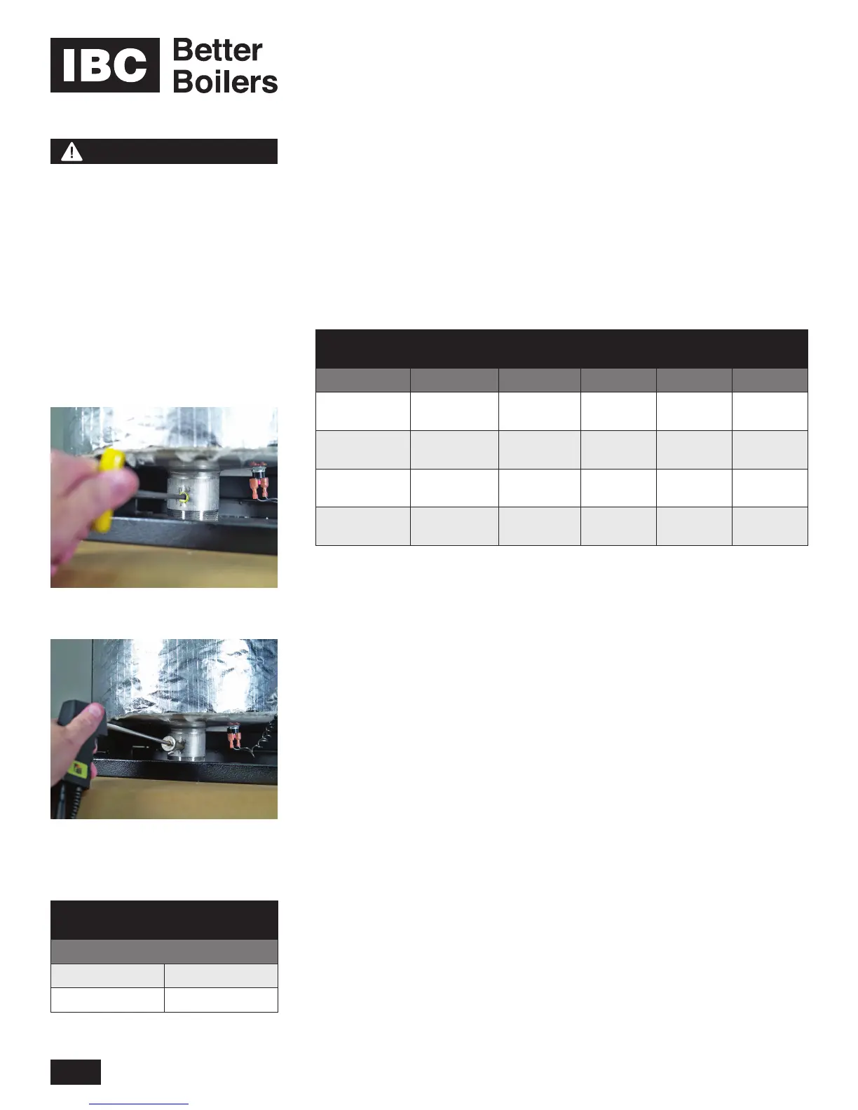
Insertion of ue gas analyzer probe
Removal of ue gas test port plug
MODEL
NUMBER
HIGH FIRE
INPUT
NATURAL GAS OR PROPANE
Table 3: Rated input of a converted
boiler / water heater
 Loading...


