1. Connect the boiler to a dedicated (max.)15 Amp
breaker.
2. Wire incoming 120 VAC to the black and white wires
labeled “AC In” in the eld wiring box.
3. Ensure that the boiler is properly bonded (grounded).
4. Wire the primary/boiler pump to the yellow and
white wires labeled “Boiler Pump”.
Refer to the “Wiring
Diagrams” section in
the Installation and
Operating Instructions
manual (Appendix) for
more information.
• For multiple-boiler setup, use a secondary loop sensor.
• For zone valves or external peripherals such as wi-
thermostats, use external transformers.
Note: If a load is dened as Reset Heating, the outdoor
sensor must be used for proper operation.
Electrical continued (Section 3.13)Water Piping (Section 3.11)
• Place air separators at the highest point.
• Install the pressure relief valve on the outlet piping of
the boiler in a vertical position. Do not use an isolation
valve between the boiler and relief valve.
• Support all piping with appropriate piping brackets.
• Plumb an appropriately sized expansion tank and make
up the water station into a tting on the suction side of
the circulator.
• Size boiler piping and pump for the BTU output of the
boiler.
For non-oxygen barrier piping systems, use a dirt separator
and/or a side stream lter. Ensure that the system is free of
iron components, and treat with an inhibitor.
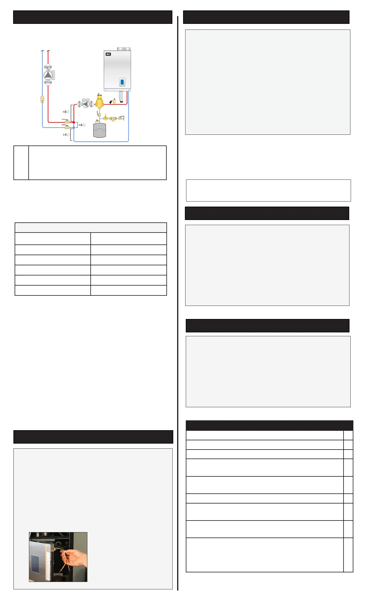
We recommend that you always use a primary/secondary
piping conguration (see below for a basic conguration).
In the case of hard water, use distilled or puried water (but
not reverse-osmosis). Glycol systems must use propylene
glycol. For large volume systems, the optimum hardness is
≤2 grains.
Water Chemistry Allowable Limits
Acidity pH 6.6 - 8.5
Chloride < 125 mg/l
Iron < 0.3 mg/l
Copper <0.1 mg/l
Conductivity
<
400μS/cm (at 77°F / 25°C)
Water Hardness
<
7 grains
Load Setup
1. On theV-10 Touchscreen controller bottom navigation
bar, tap the Setup icon
2. Select a load and then select the load type.
3. Accept the defaults, or change any of the settings.
You can nd more substantial settings in More >
Advanced Setup
4. Tap the Save button.
Manual Pump Purge
After the system is pressurized and you have dened loads,
perform a manual pump purge to ensure air is purged.
On the touchscreen controller, go to More> System
Settings > Site Settings>Set Manual Pump Purge to
"On">OK > Save.
The manual pump purge runs until it is turned off, or when
there is a call for heat.
Electrical (Section 3.13)
5. Wire the respective load pumps into the TB1 Terminal;
for example, PV1, 2, 3, 4.
6. Wire thermostats or end switch dry contacts to Therm
24 Vac, and then connect the other wire to Therm 1, 2,
3, 4 corresponding to the load pump PV1, 2, 3, 4.
7. For a DHW load, wire either an Aquastat to the
appropriate Therm. connection or a 10K Ω type II/B
curve thermister to the DHW sensor connection.
The boiler requires proper grounding, which conforms to all
electrical codes, ensuring proper ame rectication.
Checklist
Treated water or Polypropylene glycol mixture in the pipes.
□
Boiler system is pressured and ushed ≥ 8 psi.
□
All gas connections soap-tested for leaks and now leak free.
□
Voltage supply to the boiler tested for voltage (nominal 120
Vac), polarity, and properly grounded.
□
The boiler requires a dry set of contacts in the Therm
connections, an external sensor, or External Control signal.
□
Boiler power turned on.
□
Use “Setup” in the touchscreen controller to set up the
required loads. See above for instructions.
□
Steps followed in the “6.3 Commissioning” section of the
Installation and Operating Instructions manual.
□
Completed the Installation & Commissioning Report
in the Installation and Operating Instructions manual -
Combustion Readings recorded.
CO
2
_________
_
% O
2
________ % CO _______ppm
□
①
Closely-spaced tees: install tees with straight
piping (min. pipe diameter lengths as shown), with
tees maximum 4 pipe diameters apart with no
restrictions between ttings
 Loading...


