Table 8. Memory-mirroring mode DIMM population sequence
DIMMs
Number of installed
microprocessors DIMM connector
First pair of DIMMs 1 3, 6
Second pair of DIMMs 1 2, 5
Third pair of DIMMs 1 1, 4
Fourth pair of DIMMs 2 14, 11
Fifth pair of DIMMs 2 13, 10
Sixth pair of DIMMs 2 12, 9
Note: DIMM connectors 7, 8, 15, and 16 are not used in memory-mirroring mode.
When you install or remove DIMMs, the server configuration information changes.
When you restart the server, the system displays a message that indicates that the
memory configuration has changed.
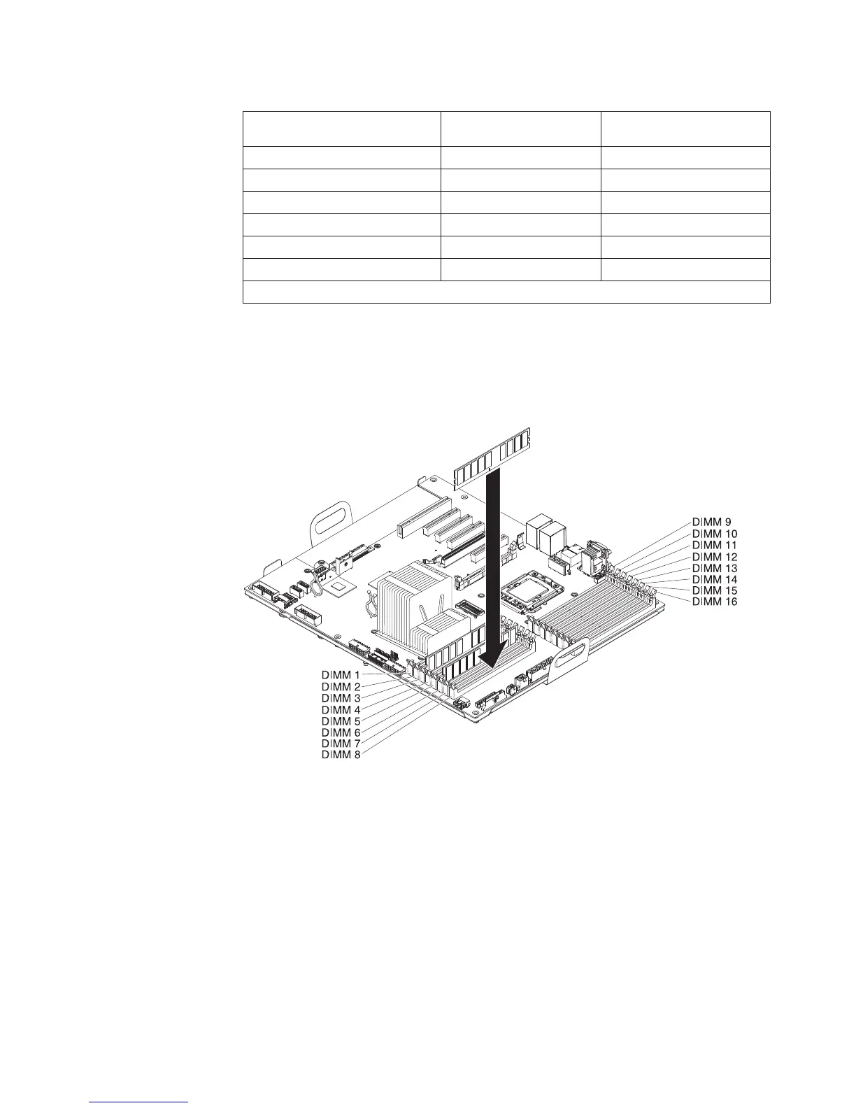
The following illustration shows how to install DIMMs on the system board.
Attention: Static electricity that is released to internal server components when
the server is powered-on might cause the server to stop, which might result in the
loss of data. To avoid this potential problem, always use an electrostatic-discharge
wrist strap or other grounding system when you work inside the server with the
power on.
To install a DIMM, complete the following steps:
1. Read the safety information that begins on page v and “Installation guidelines”
on page 35.
2. Turn off the server and peripheral devices; then, disconnect the power cords
and all external cables.
3. Remove the left-side cover (see “Removing the left-side cover” on page 48).
4. Remove the hot-swap power supply or power supplies from the server.
Chapter 2. Installing optional devices 65
 Loading...