EasyManuals Logo
Home>Icom>Tuner>AH-4

Icom AH-4 Instructions

Icom AH-4
4 pages
To Next Page IconTo Next Page
To Previous Page IconTo Previous Page
Page #3 background imageLoading...
Page #3 background image
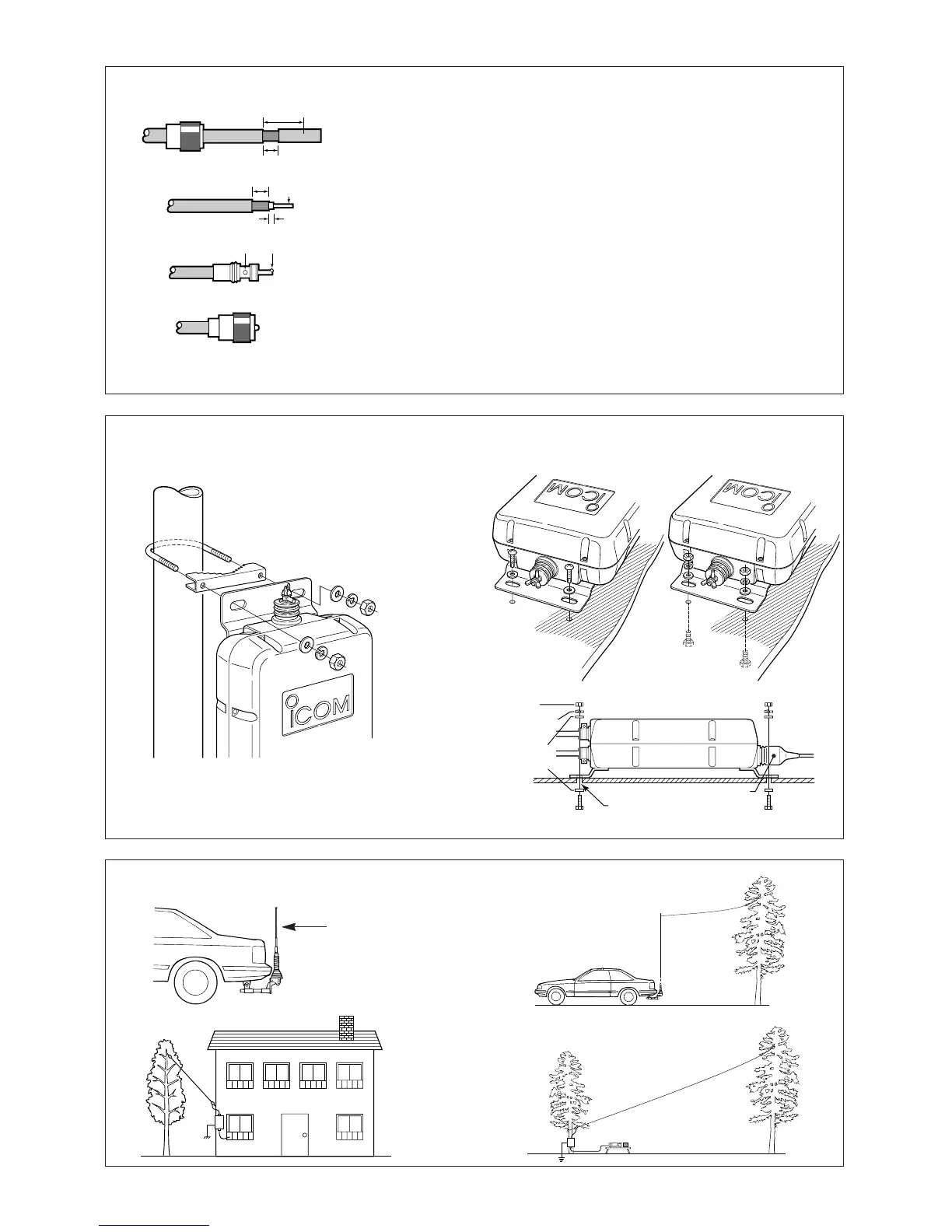
Fig. 5 MOUNTING THE AH-4
Mounting on an antenna pole
Mounting on a flat location
Fig. 6 MOUNTING EXAMPLES
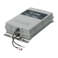
Fig. 4 PL-259 CONNECTOR SOLDERING
Slide the coupling ring over the coaxial cable. Strip
the cable jacket and pull it down to reveal 10 mm
(0.4 in) of braid.
Soft solder the exposed braid and then pull the jacket
back in place.
Strip the cable as shown at left. Tin the center con-
ductor the entire length of the exposed braid.
Slide the connector body over the cable and sol-
der as shown at left.
Screw the coupling ring onto to the connector
body.
30 mm
10 mm (soft solder)
10 mm
1–2 mm
solder solder
Soft
solder
Coupling ring
(10 mm
3
8 in)
AH-2b + long wire
AH-2b
ANTENNA ELEMENT
KIT (optional)
Nut
AH-4
Spring
washer
Flat
washer
Hex head
bolt
Drill a hole here
(diameter: 6.6–7 mm)
Weatherproof cap
Using the supplied U-bolts
Using self-tapping screws
Using nuts and bolts

Other manuals for Icom AH-4

Questions and Answers:

Question and Answer IconNeed help?

Do you have a question about the Icom AH-4 and is the answer not in the manual?

Icom AH-4 Specifications

Frequency and Impedance IconFrequency and Impedance
frequency range with antenna longer than 7 m3.5–54 MHz
frequency range with AH-2b7–54 MHz
input impedance50 Ω
Power IconPower
maximum input power120 W
tuning power required10 W (5–15 W)
rated voltage13.8 V DC ±15% (current drain less than 1 A)
Operating Environment IconOperating Environment
usable temperature range–10°C to +60°C (+14°F to +140°F)
VSWR2.0 : 1 or less
dimensions172(W) × 69.5(H) × 230(D) mm; 6[25]⁄32(W) × 6[3]⁄4(H) × 9[1]⁄16(D) in
Weight and Dimensions IconWeight and Dimensions
weight1.2 kg (2.65 lb)
dimensions172(W) × 69.5(H) × 230(D) mm; 6[25]⁄32(W) × 6[3]⁄4(H) × 9[1]⁄16(D) in

Related product manuals