|905
CONNECTION GUIDE
ALL MODE TRANSCEIVER
Thank you for choosing this Icom product.
READ ALL INSTRUCTIONS carefully and completely
before using this product.
– 1 –
1-1-32 Kamiminami, Hirano-ku, Osaka 547-0003, Japan
A7711D-2EX Printed in Japan
© 2023 Icom Inc.Feb. 2023
– 4 –
Icom and the Icom logo are registered trademarks of Icom Incorporated (Japan) in Japan, the United States, the United Kingdom, Germany,
France, Spain, Russia, Australia, New Zealand, and/or other countries.
Connecting the RF unit and the controller
TIP:
To prevent water from seeping into the connection
After connecting, cover the connectors and Ferrite EMI lter
with the supplied or user supplied rubber vulcanizing tape.
About an external DC power supply
The transceiver needs:
• 13.8 V DC
• A power supply with an over current protective line, and
low voltage uctuation or ripple.
L Conrm that the power supply is OFF before connecting
the DC power cable.
Connect the RF unit and the controller, as shown below.
LPrepare antennas and cables, suitable for your operating
environment.
NOTE: Attach the connector cap when no equipment is
connected.
Supplied rubber
vulcanizing tape
Rubber
vulcanizing tape
(User supplied)
Connect the antennas.
1
Coaxial cable
(User supplied)
To the antenna for the 144 MHz,
430 MHz, and 1200 MHz band
To the antenna for
the 2400 MHz band
To the antenna for
the 5600 MHz band
Coaxial cable
(User supplied)
RF unit
RF unit’s top panel
RF unit’s bottom panel
Controller
To
[DC 13.8 V] jack
Supplied DC
power cable
Control cable*
To [RF UNIT] connector
Connect the DC power
cable, and then push
[POWER] to turn ON the
transceiver.
3
Connect the RF unit
and controller with the
control cable.
2
Important
FIRST, CAREFULLY READ BASIC MANUAL that is boxed
with the transceiver.
SAVE THESE INSTRUCTIONS— These instructions
contain installation instructions for the IC-905.
The Connection Guide for German, Spanish, French, and
Italian is at the end of the Basic manual for each respective
language.
* The following cables are usable, depending on your operating environment.
Supplied control cable: 5 m (16.4 feet)
Optional OPC-2513 control cable: 20 m (65.6 feet)
Optional OPC-2509 control cable: 50 m (164.0 feet)
Requirements for attaching and connecting
Control cable for connecting
Controller and RF unit
(5 m: 16.4 feet)
GPS antenna
Bracket
Assembled screws
for bracket
(6 × 15 mm)
Screws and washers
for attaching to a pole
U-boltsPole clampsDC power cable
(1.5 m: 4.9 ft)
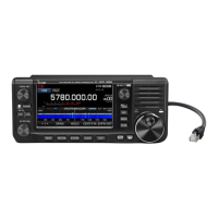
IC-905
(Controller)
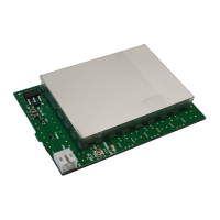
IC-905
(RF unit)
Rubber
vulcanizing tape
BE CAREFUL! When you install the IC-905’s RF unit and
antenna, wear gloves to avoid cutting your hand on the
sharp edges of the metal parts or antenna.
Icom is not responsible for any building breakage, any
damage resulting from a drop of the mounting bracket from
a high place or unstable site, or any personal injury or any
accident in any other case. Be sure to consult an expert
engineer for installation help.
Supplied control
cable
To the RF unit
Ferrite EMI lter
Attach the Ferrite EMI lter to
the DC power cable.