o
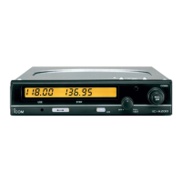
ICOM IC-A200
IMPORTANT
READ THESE INSTALLATION INSTRUC-
TIONS CAREFUllY beforeattemptingto install
the IC-A200 in an aircraft. This sheet contains important
safety instructions for the IC-A200.
NEVER install the transceiver where normal navi-
gation of the aircraft may be hindered.
NEVER install an antenna near any aircraft projection,
engine, or propeller.
INSTAll a circuit breaker between the aircraft battery
and the IC-A200.
NEVER install the transceiver in an aircraft with a 24 V
battery. The transceiver operates with 13.8 V DC.
Check operation after installation.
Protect channel content CANNOT be changed by a
customer.
INSTALLATION INSTRUCTIONS
INSTALLATION PROCEDURE
Install the IC-A200 according to the following procedure.
CD Check the quantity of parts. Refer to UNPACKING.
@ Prepare miscellaneous items required for instal-
lation. Referto MISCELLANEOUSITEMS.
<ID Prepare required wiring. Refer to MOLEX CONNEC-
TOR ASSEMBLY, COAXIAL CABLE ASSEMBLY and
WIRING.
@ Assemble supplied mounting bracket and other
parts. Refer to RACK MOUNT ASSEMBLY.
<ID Cut the mounting hole. Refer to MOUNTING HOLE.
@ Mount the IC-A200 into the mounting bracket. Refer
to RACK MOUNTING.
(/) Check the IC-A200 operation. Refer to OPERATION
CHECK.
@ Set protect channels, if required. Refer to MEMORY
PROTECTION.
UNPACKING
The following parts are supplied with the IC-A200.
Inspect the quantity of each part carefully.
CD
o
o
o
o
o
CD Mounting bracket 1
@ Molex connector (4338-15) 1
<ID Molex terminals (4366-GL) 30
@ Screws (No.4 x 1/2) 2
<ID BNC L-shaped antenna connector 1 set
@ Washer (Icom washer V) 1
(/) C-shaped ring 1
@ Antenna cable clip 1
@ Self-crimping nut (No. 6) 1
Make sure you have received all parts and that there is
no shipping damage.
@
o
@
@)
@
1
@
~
@
T
@ @) @
c:=:J c:=:J n==:rIn==:rI
@
D
@ Nut (No. 6) 1
@ Screw (No.6 x 1/2) 1
@ Crimp nuts (No. 6) 6
@ Screw (No.6 x 1/2) 6
@ COMM1 sticker 1
@ COMM2 sticker 1
@ Fuses (5 A) 2
@ Molex polarizing key 1

 Loading...