Printed in Japan
© 2016–2018 Icom Inc
Basic Issue: May 10/16
Revision 6: Feb 9/18
12421 Willows Road NE, Kirkland, WA 98034, U.S.A
Printed on recycled paper with soy ink.
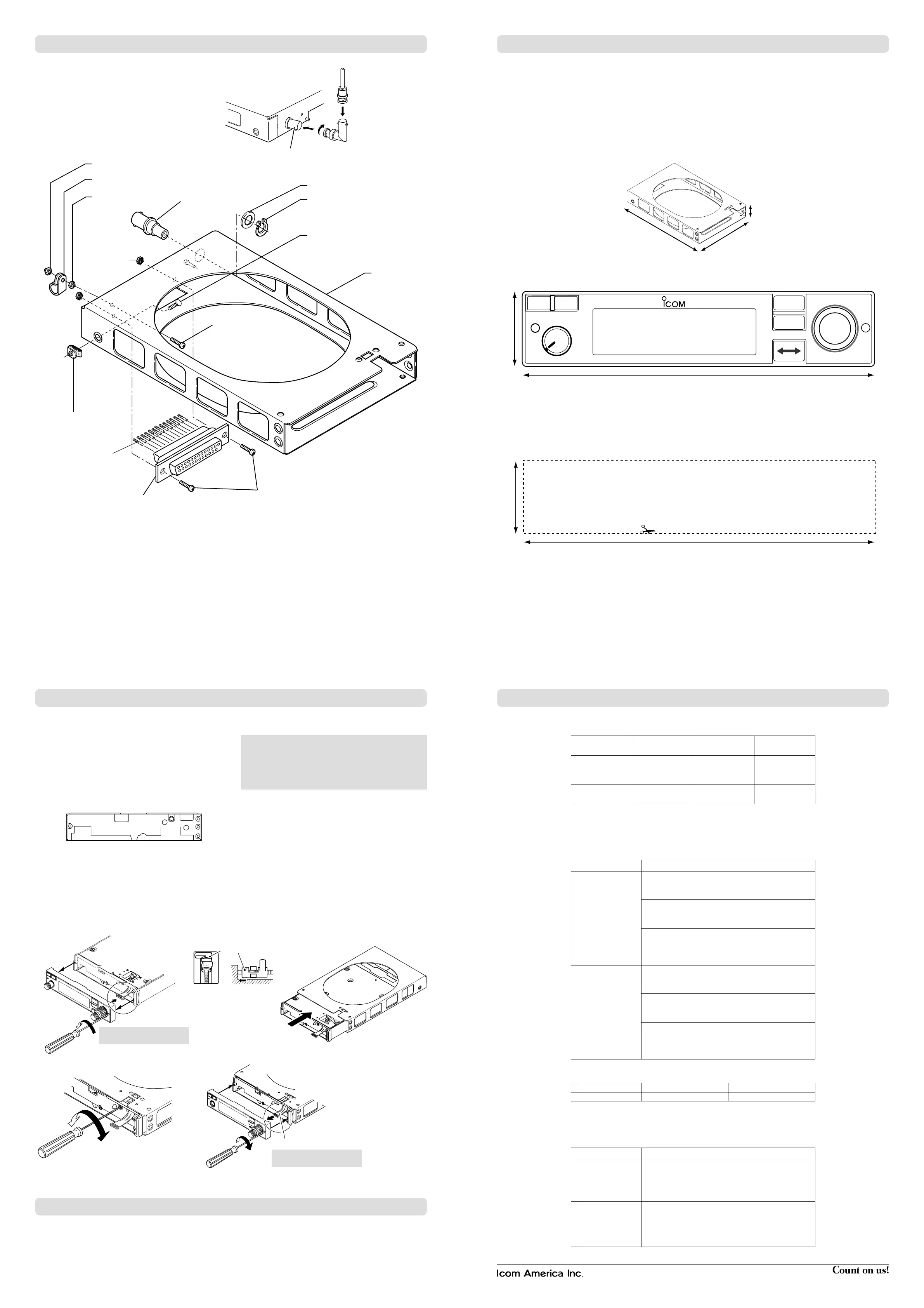
L-type BNC
connector
(User supplied, if required)
Coaxial
connector
y BNC-LP
y BNC-LP
!2 Nut
o Antenna cable clip
!0 Self-crimping nut
u Washer
i C-shaped ring
!4 Screws
!1 Screw
r Screws Bind UNC
q Mounting
bracket
w D-sub 25 pin connector
!3 Crimp nut
q Mounting
bracket
e Connector pins
t K-Lock Nut
. MOUNTING BRACKET ASSEMBLY
D Notes for marking the mounting hole
The transceiver can be mounted securely in the supplied
mounting bracket.
Remember to allow adequate space for installation of
cables and connectors.
When installing two or more transceivers in a stack, the
mounting bracket should be 1.3 mm
(0.05″) apart.
The mounting bracket has 0.6 mm
(0.024″) dimples in the
top, bottom, and both sides for proper spacing.
Mark and cut the mounting holes.
To support the mounting bracket, the rear mounting bosses
should be attached to the airframe.
⁄0 MARKING A MOUNTING HOLE
D Mounting bracket dimensions
160 mm (6.3″)
33 mm (1.3″)
260 mm (10.2″)
D Front panel dimensions
160 mm (6.3″)
34 mm (1.3″)
RCL
MEM
OFF
VOL
PUSH
TEST
COMM
DUAL
EC
118.00
128.10
Allow space for the front panel as shown above.
D Template
Cut out dimensions for the mounting bracket as follows.
160 mm (6
5
⁄
16
″)
33 mm (1
5
⁄
16
″)
Fig. 1
Fig. 4
Fig. 3
Fig. 5
Fig. 1
Fig. 6Fig. 5
Fig. 7
Clockwise: For installation.
Counterclockwise: For removal.
CAUTION: Treat the cable with
care when disconnecting it.
Clockwise: For attaching.
Counterclockwise: For removal.
Cable
CAUTION: Treat the cable with
care when connecting it.
Fig. 2
Surface
The flat cable
Fig. 2 Fig. 4Fig. 3
Screw 4 revolutions Unscrew a quarter
revolution
• Metal catch position
Metal catch
Metal catch
⁄1 MOUNTING TO THE BRACKET ⁄3 INFORMATION
D Transceiver installation
1. Remove the front panel from the transceiver’s main unit.
- Use a
3
⁄32″ allen driver.
- Carefully disconnect the cable from the front panel.
(Fig. 1)
2. Insert a
3
⁄32″ allen driver into the lock screw and rotate
the driver counterclockwise until the metal catch
touches the back of the lock chassis. (Fig. 2)
Main unit front view
3. Insert the main unit (transceiver) into the mounting
bracket. (Fig. 3)
4. Turn the lock screw clockwise until the main unit
(transceiver) is fixed to the bracket. (Fig. 4)
5. Connect the cable. (Fig. 5)
6. Attach the front panel and tighten the allen screws.
(Fig. 5)
CAUTION: Make sure that the cable between the
transceiver and front panel is securely connected. The
transceiver may not function properly when loose or when
a wrong connection is made.
Improper cable connection can cause damage and result
in a non-warranty repair.
D Transceiver removal
The transceiver can be easily removed from the mounting
bracket, if required.
1. Remove the front panel from the transceiver's main unit.
- Use a
3
⁄32″ allen driver.
- Carefully disconnect the cable from the front panel.
2. Insert a
3
⁄32″ allen driver into the lock screw and rotate
the driver counterclockwise until the metal catch
touches the back of the lock chassis.
3. Slowly pull the transceiver out from the mounting bracket.
4. Connect the cable to the front panel.
5. Attach the front panel and tighten the allen screws.
D TSO Authorization Reference
Function TSO/RTCA
Applicable SW
P/Ns
DO-178C Level
Equipment That
Prevents Blocked
Channels
TSO-C128a
DO-207
A220-0615-0028 C
COM Transceiver
TSO-C169a
DO-186B
A220-0615-0028 C
(1) Software Part Number
(
A220-0615
) - ( 0028 )
(Part Number) - (Version) Version to be incremented on a minor software change
D TSO Deviation list
TSO/ETSO Deviation
TSO-C128a
1. Icom was granted a deviation from the TSO to mark
the exterior of the unit with the serial number instead
of the date of manufacture.
2. Icom was granted a deviation from the TSO to use
RTCA/DO-160G instead of the earlier version as the
standard for environmental conditions and tests.
3. Icom was granted a deviation from the TSO to use
RTCA/DO-178C instead of the earlier version to
demonstrate compliance for the verification and
validation of computer software.
TSO-C169a
1. Icom was granted a deviation from the TSO to mark
the exterior of the unit with the serial number instead
of the date of manufacture.
2. Icom was granted a deviation from the TSO to use
RTCA/DO-160G instead of the earlier version as the
standard for environmental conditions and tests.
3. Icom was granted a deviation from the TSO to use
RTCA/DO-178C instead of the earlier version to
demonstrate compliance for the verification and
validation of computer software.
• FCC Grant of Equipment Authorization
Model FCC ID IC ID
IC-A220 AFJ297410 202D-297410
D Non-TSO function list
These functions operate per the system requirements for this transceiver and do not interfere with the TSO MOPS compliance.
Function Description
Weather Channels
Reception
The radio provides reception of the weather channels
which Icom America evaluated as part of the RTCA/
DO-160G and RTCA/DO-178C test/verication process
and additional system level tests were also performed.
Two Station Intercom
The radio provides a user interface to select two
station intercom as an option to the pilot. This function
was tested as part of the RTCA/DO-160G and the
RTCA/DO-178C test/verication process and additional
system level tests were also performed.
Check the following points after transceiver installation.
- Polarity of the power supply.
- NO interference caused to other equipment.
- NO noise or interference from other equipment.
- VSWR is less than 2.5:1.
- Communication capability on both the highest and lowest
communication frequencies, if possible.
⁄2 OPERATION CHECK

 Loading...


