2
1
PANEL DESCRIPTION
1
2
3
4
5
6
7
8
9
10
11
12
13
14
15
16
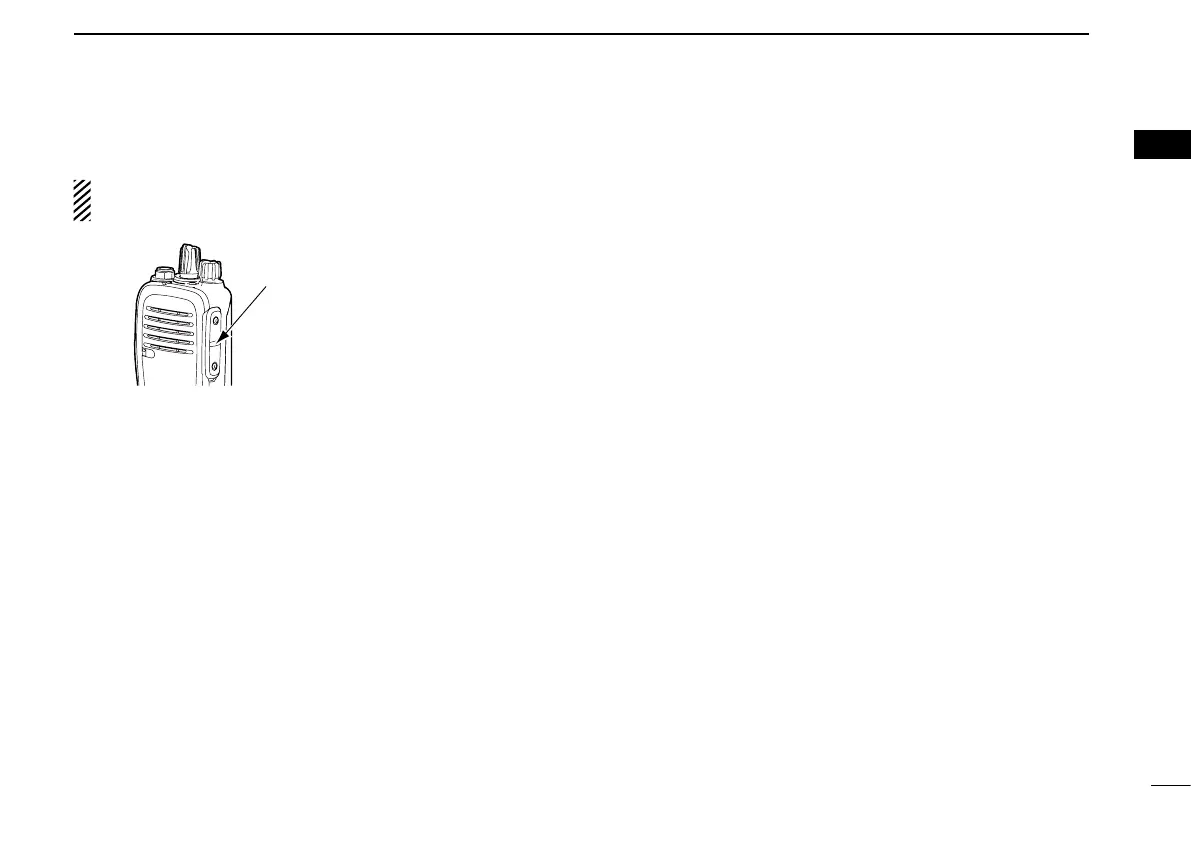
r SPEAKER-MICROPHONE JACK
Connect optional equipment. ➥
NOTE: After turning OFF the transceiver, connect or dis-
connect the optional equipment.
t FUNCTION DISPLAY
Displays a variety of information such as the operating ➥
channel number, channel name, User Set mode con-
tents, and so on. See page 3 for details.
y DEALER-ASSIGNABLE KEYS [P0]–[P3]
Desired functions can be independently programmed ➥
by your dealer.
u DEALER-ASSIGNABLE KEYS
[UP] or [Upper]*, [DOWN] or [Lower]*
Desired functions can be independently programmed ➥
by your dealer.
* Names for the non-display type transceivers
i PTT SWITCH [PTT]
Hold down to transmit, release to receive. ➥
o LED INDICATOR
Lights red while transmitting. ➥
Lights green while receiving a signal, or when the ➥
squelch is open.
Lights or blinks orange when the matched 2-Tone or ➥
5-Tone is received, depending on the presetting.
You should charge the battery when the indicator slow- ➥
ly blinks.
You must charge the battery when the indicator blinks ➥
fast.
!0 ANTENNA CONNECTOR
Connects the supplied antenna. ➥
Jack cover
NOTE: Attach the jack cover when
optional equipment is not used.
 Loading...