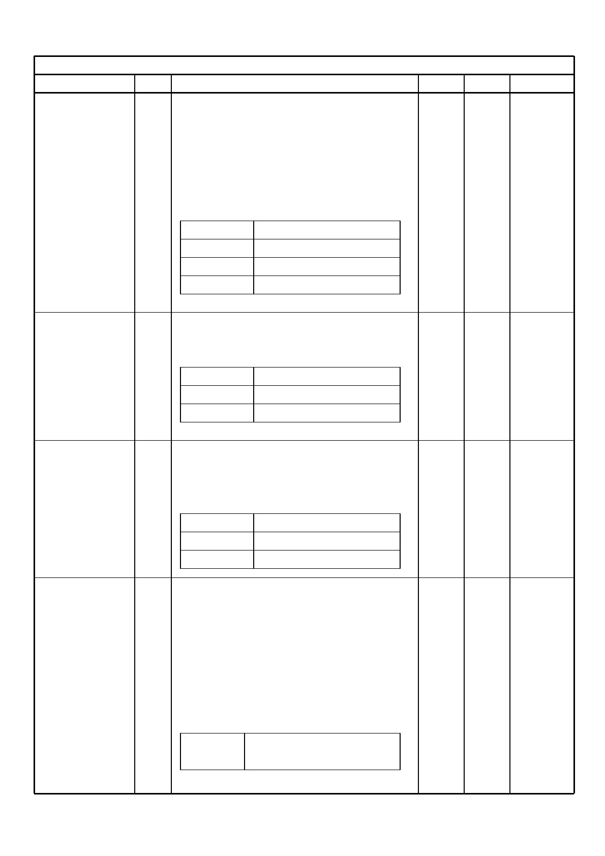
ADJUSTMENT
Adjustment No. Adjustment Condition & Tuning Value Ref. No. CK. Point
TX Output Adjust so that the transceiver power voltage
Adjustment is stable with the voltage from the power
terminal at 7.5V during TX.
Use adjustment software to adjust the
adjustment output to the values below.
Adj. Freq. Greatest Low Band Freq.
Hi Power 5.0W 5.0W Adj. Soft ANT Con
L2 Power 2.0W 2.0W
L1 Power 1.0W 1.0W
TX Output Check Check that the in-band TX output is within
the specifications below.
Hi Power 4.0~6.0W 4.0-6.0W ANT Con
L2 Power 1.2~2.8W 1.2-2.8W
L1 Power 0.5~2.0W 0.5-2.0W
Current Check at Check that the in-band power consumption
TX is within the specifications below. 4.0-6.0W ANT Con
Hi Power Less than 2.0A Less 2.0A PWR Con
L2 Power Less than 1.5A Less 1.5A
L1 Power Less than 1.2A Less 1.2A
Checking Spurious Connect a spectrum analyzer to the ANT
terminal through an attenuator. Set the
attenuation so that the spectrum analyzer
does not distort.
Set the transceiver to TX and when at Hi
power, check that spurious is less than the
value below in the bandwidth.
Spurious Less than –65dB of the Less than ANT Con
fundamental wave -65 dB

 Loading...