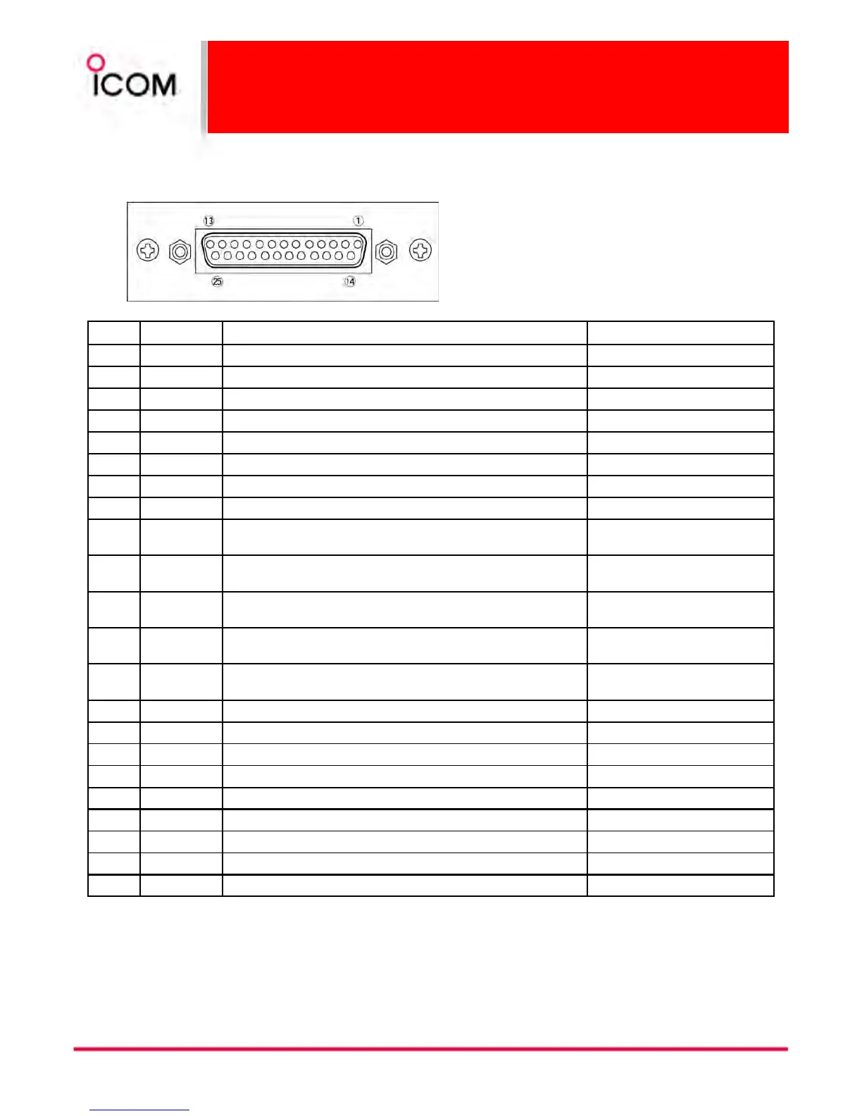
3-1-3 Connector Description
Accessory connector
Accessory connectorAccessory connector
Accessory connector
Pin No.
Pin No.Pin No.
Pin No. Pin Name
Pin NamePin Name
Pin Name Description
DescriptionDescription
Description Specification
SpecificationSpecification
Specification
1 BUSY OUT Output terminal for busy signal. Open collector=OFF, 0 V=ON
2 COAXIAL SW Output terminal for coaxial switching (antenna switching) Signal. Open collector=OFF, 0 V=ON
3 M/S IN Input terminal for master/slave signal. +5 V pull up, Active=L
4 D1 Input terminal for selecting memory channel. +5 V pull up, Active=L
5 D3 Input terminal for selecting memory channel. +5 V pull up, Active=L
6 EXT RPT/BASE Input terminal for repeater/base operating mode switching signal. +5 V pull up, Active=L
7 EXT MONI Input terminal for monitor function. +5 V pull up, Active=L
8 EXT DTCS Input terminal for continuous tone (CTCSS/DTCS) signal. Input impedance: 100 kΩ (approx.)
9 EXTMOD IN B
Input terminal for the modulation signals applied to input of the
splutter filter circuit.
Input impedance: 600 Ω (approx.)
15
10 EXTMOD IN A
Input terminal for the modulation signal applied to input of the pre-
emphasis circuit via the bandpass filter.
Input impedance: 600 Ω (approx.)
11 AF OUT
Output terminal for AF signals from the AF detector circuit via the
bandpass filter. Output level is fixed, regardless of [AF] control.
Output impedance: 1 kΩ (approx.)
12 DISC OUT
Output terminal for AF signals from the AF detector circuit.
Output level is fixed, regardless of [AF] control.
Output impedance: 1 kΩ (approx.)
13 +15V
Output terminal for +15V DC while in AC operation. (While in DC
operation, same as input DC.)
Output current: Less than 1 A
14 TX OUT Output terminal for transmission state. Open collector=OFF, 0 V=ON
15 M/S OUT Output terminal for master/slave signal. Open collector=OFF, 0 V=ON
16 D0 Input terminal for selecting memory channel. +5 V pull up, Active=L
17 D2 Input terminal for selecting memory channel. +5 V pull up, Active=L
18 D4 Input terminal for selecting memory channel. +5 V pull up, Active=L
19 EXT PTT Input terminal for PTT signal. +5 V pull up, Active=L
20 RSSI Output terminal for RSSI (Received Signal Strength Indicator) Signal. Output impedance: 1 kΩ (approx.)
21-24 AGND Analog ground
25 DC GND Ground for +15 V DC
 Loading...