5 - 3
5-3 TRANSMIT ADJUSTMENT
ADJUSTMENT ADJUSTMENT CONDITION OPERATION VALUE
TRANSMIT
OUTPUT
POWER
1 • Channel : CH16 (156.800 MHz)
• Output power : High
• Connect an RF power meter to the ant-
enna connector.
• Transmitting
Adjust R135 (PWR). 23.5 W
DEVIATION 1 • Channel : CH16 (156.800 MHz)
• Output power : Low
• Connect an audio generator to the ‘MIC’
line (see the picture below), and set as;
Frequency : 1 kHz
Level : 140 mV
• Connect an FM deviation meter to the ant-
enna connector through an attenuator,
and set as ;
HPF : OFF
LPF : 20 kHz
De-emphasis : OFF
Detector : (P–P)/2
• Transmitting
Adjust R184 (DEV). ±4.3 kHz
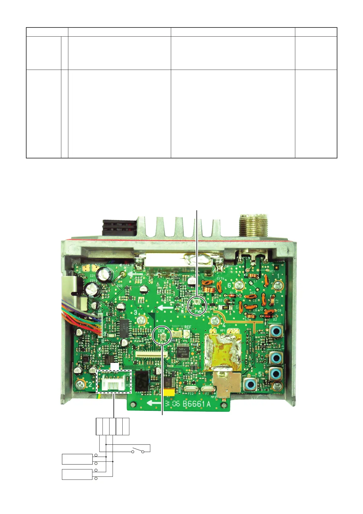
• ADJUST&CHECK POINTS LOCATION (TRANSMIT)
KEYM
GND
MIC
MICG
PTT
15
+
–
–
+
AC millivoltmeter
Audio generator
[PTT]
J2
R135 (PWR)
TRANSMIT OUTPUT POWER
ADJUSTMENT POINT
R184 (DEV)
DEVIATION
ADJUSTMENT POINT

 Loading...