INSTRUCTIONS
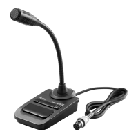
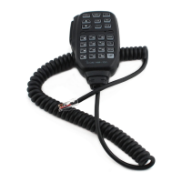
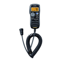
DESKTOP MICROPHONE
SM-30
Thank you for purchasing the SM-30
d e s k t o p m i c r o p h o n e .
This is a unidirec-
tional, electret microphone designed
for base station operation with an Icom
transceiver.
Please read these instructions thorough-
ly before using the microphone.
PRECAUTIONS
CAUTION: NEVER expose the microphone
to rain, snow or any liquids.
CAUTION: NEVER let metal, wire, etc.
touch any internal part of the microphone.
CAUTION: NEVER touch or operate the
desktop microphone with wet hands.
DO NOT place the microphone in exces-
sively dusty environments or in direct sun-
light.
DO NOT use harsh solvents such as ben-
zine or alcohol to clean the microphone,
as they can damage the microphone’s sur-
faces.
Place the microphone in a secure place to
avoid inadvertent use by children.
This microphone is for the specified Icom
transceivers only! — The microphone can-
not be used with a non-Icom transceiver
since the power is supplied from the con-
nected transceiver.
About CE
The SM-30 complies with the
essential requirements of the
2004/108/EC directive for
Electromagnetic Compatibility.
• Microphone type : Unidirectional electret condenser microphone (preamp built-in)
• Output impedance : 600 Ω ±30% (at MIC GAIN: Max)
• Sensitivity : –28 dB ±4 dB (0 dB=1 V/Pa, at 1 kHz)
• Power requirements : 8 V DC (supplied from the transceiver)
• Cable length (approx.) : 1 m; 3 ft 3
3
⁄8 in
• Weight (approx.) : 350 g; 12.3 oz
All stated specifications are subject to change without notice or obligation.
1-1-32 Kamiminami, Hirano-ku, Osaka 547-0003, Japan
A-6829X-1G-q Printed in Japan
© 2010 Icom Inc.
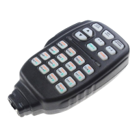
PART NAMES AND FUNCTIONS
Icom, Icom Inc. and the Icom logo are registered trademarks of Icom Incorporated (Japan) in Japan,
the United States, the United Kingdom, Germany, France, Spain, Russia and/or other countries.
SPECIFICATIONS
D PLUG PIN ASSIGNMENTS
The pins are described from the direction of the arrow in the illustration.
y GND (PTT ground)
t PTT
r No connection
q Microphone output
w 8 V DC input
e No connection
u GND (Microphone ground)
i No connection
D TOP VIEW
q PTT SWITCH
Push to transmit, then release to re-
ceive.
w PTT LOCK SWITCH
Push to continuously transmit. The
transmission continues until pushing this
switch again.
e PTT LOCK INDICATOR [LOCK]
Lights red when the PTT lock switch
(w) is ON.
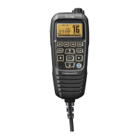
D BOTTOM VIEW
r MIC GAIN VOLUME [MIC GAIN]
Rotate to adjust the microphone out-
put level.
• Use this control as an adjunct to the
microphone gain setting of the con-
nected transceiver.
Rotating the control too far clockwise
may result in an output level that is
too high and transmit signal distor-
tion.
t LOW CUT SWITCH [LOW CUT]
Cuts out the low frequency components
of input voice signals.