4
5
2
6
7
1
3
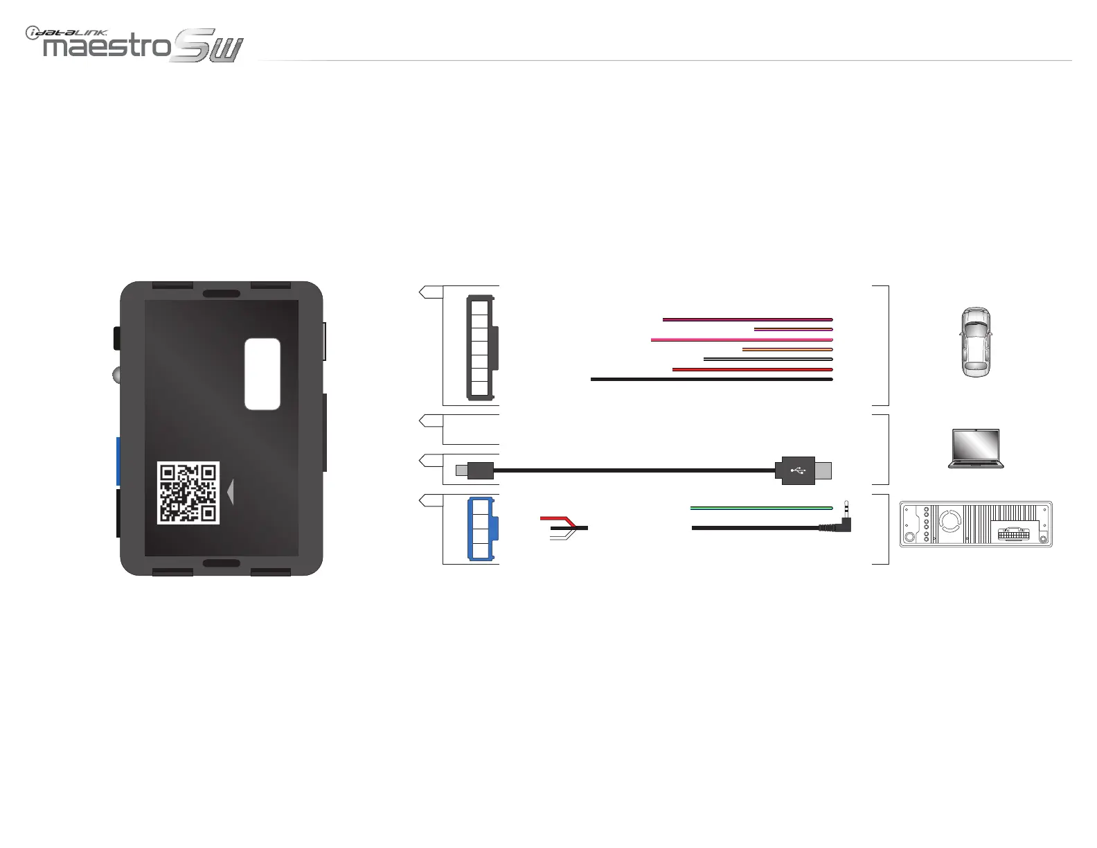
A
USB
C
1
2
3
4
B
VEHICLE
WEB
01 PURPLE/RED - SWI CIRCUIT 1 INPUT
02 PURPLE/YELLOW - SWI CIRCUIT 1 OUTPUT/ANALOG 1 INPUT
03 PINK/RED - SWI CIRCUIT 2 INPUT
04 PINK/YELLOW - SWI CIRCUIT 2 OUTPUT/ANALOG 2 INPUT
05 BLACK/WHITE - SWI GROUND FEED (-) OUTPUT
06 RED - ACCESSORY POWER +12V INPUT
07 BLACK - GROUND
C
LED
PROGRAMMING
BUTTON
USB
A
B
MODULE
BACK VIEW
01 BLUE/YELLOW - RADIO CONTROL 1 OUTPUT
02 RED
04 WHITE
03 BLACK
AFTERMARKET RADIO
RADIO CONTROL 2 OUTPUT
WEBLINK UPDATER CABLE (NOT INCLUDED)
INSTALLATION OVERVIEW - 1 OF 1
www.maestro.idatalink.comAutomotive Data Solutions Inc. © 2012
ADS-SW(SI)-ALL01-AS-IG-EN
PagE 3 Of 8
• 20120913
DOC.: #9729
 Loading...