12
DOC No: 8540 REV E
13
DOC No: 8540 REV E
The two fault signals provide diagnostic feedback to the user’s control
system. These use the common ground to provide HI or LOW signals.
When both Fault Signals indicate HI, the EagleDrive is operating normally
(no faults detected). Signals are driven with 5.6kohm pull-up resistors to the
internal 5V and should be monitored with a high impedance device (R
load
>
100kohms).
Caution: Do not short Fault Signals to ground or EagleDrive will not
operate properly.
Fault Signal Out
Fault
Signal 1
Lead 8
Brown
Fault
Signal 2
Lead 7
Blue
Fault
Description
Drive
Condition
Reason for
Fault
Remedy
0 0 Under
Voltage
Disabled Voltage
supply less
than 8.5V
Ensure proper supply voltage,
check power and ground
connections
0 0 Over
Temperature
Operating Internal
component
temperature
greater than
170º C
Reduce load or increase
cooling
0 0 Logic Fault Disabled Drive cannot
locate the
magnets
inside the
pump
Ensure pump is correctly
attached to EagleDrive
1 0 Internal Short Disabled Drive
components
have failed
Reset EagleDrive by
disconnecting and restoring
power supply connection,
if problem persists, contact
Micropump for a replacement.
0 1 Low Load
Current
Operating Drive
components
have failed
Reset EagleDrive by
disconnecting and restoring
power supply connection,
if problem persists, contact
Micropump for a replacement.
1 1 None Operating No Fault
CAUTION
1
2
3
4
5
7
8
9
6
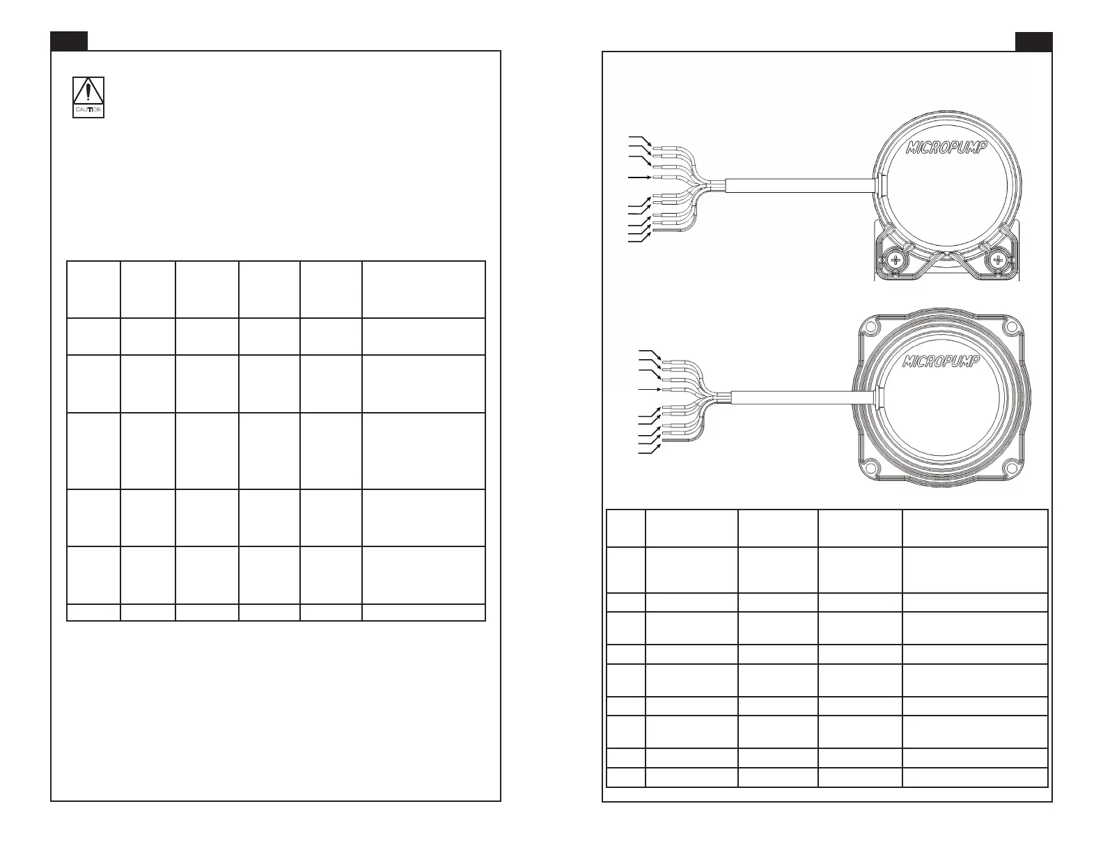
MODEL DEMSE
1
2
3
4
5
7
8
9
6
MODEL DEELE
LEAD FUNCTION GRAY CABLE
WIRES
BLACK CABLE
WIRES
1 POWER RED RED +12 to +36 VDC, Class 2
(SELV), Reverse-polarity
protected
2 SPEED PWM IN VIOLET YELLOW Ground if not used
3 GROUND BLACK BLACK Common isolated from motor
housing
4 FAULT OUT BROWN BROWN Fault Signal 1
5 FWD/REV ORANGE ORANGE Forward (fl oat and insulate),
Reverse (ground)
6 FAULT OUT BLUE BLUE Fault Signal 2
7 TACH OUT GREEN GREEN 5 V square wave-2 pulses per
revolution
8 SPEED 0-5 IN YELLOW WHITE Control signal in, 0-5 VDC
9 SHIELD BARE BARE Connected to Common
EagleDrive Lead Wire Assignments
 Loading...