-46-
Introduction
3.5.2 I/O Module
Two I/O modules (AM600-0808ETNE and AM600-1616ETNE) that support EtherCAT remote
communication are provided. The detailed specications are as follows:
1) Basic specications
Item Specications
Power specications 24 VDC (20.4 VDC to 28.8 VDC) (–15% to +20%)
Communication protocol EtherCAT industrial real-time bus protocol
Max. communication baud rate 100 Mbps
Network port/network cable Standard network ports with Cat5e network cables shorter than 100 m
Station number range
Set the DIP switch between 1 and 255 or use the value automatically
assigned by the network bus.
■
The following table lists the performance indicators:
Item Specications
Communication protocol EtherCAT
Service supported CoE (PDO
,
SDO) and FoE
Synchronization mode I/O uses a DC-distributed clock or I/O synchronization.
Physical layer 100BASE-TX
Baud rate 100 Mbit/s (100Base-TX)
Duplex mode Full duplex
Topological structure Linear topological structure
Transmission medium For the network cable
,
see
"Chapter 5 Wiring"
.
Transmission distance Less than 100 M between two nodes
EtherCAT frame length 44 bytes to 1498 bytes
Process data A single frame can contain a maximum of 1486 bytes.
Synchronization jitter of two slaves < 1 μs
Refresh time
1000 digital inputs and outputs: approximately 30 μs; 32 servo axes:
approximately 100 μs
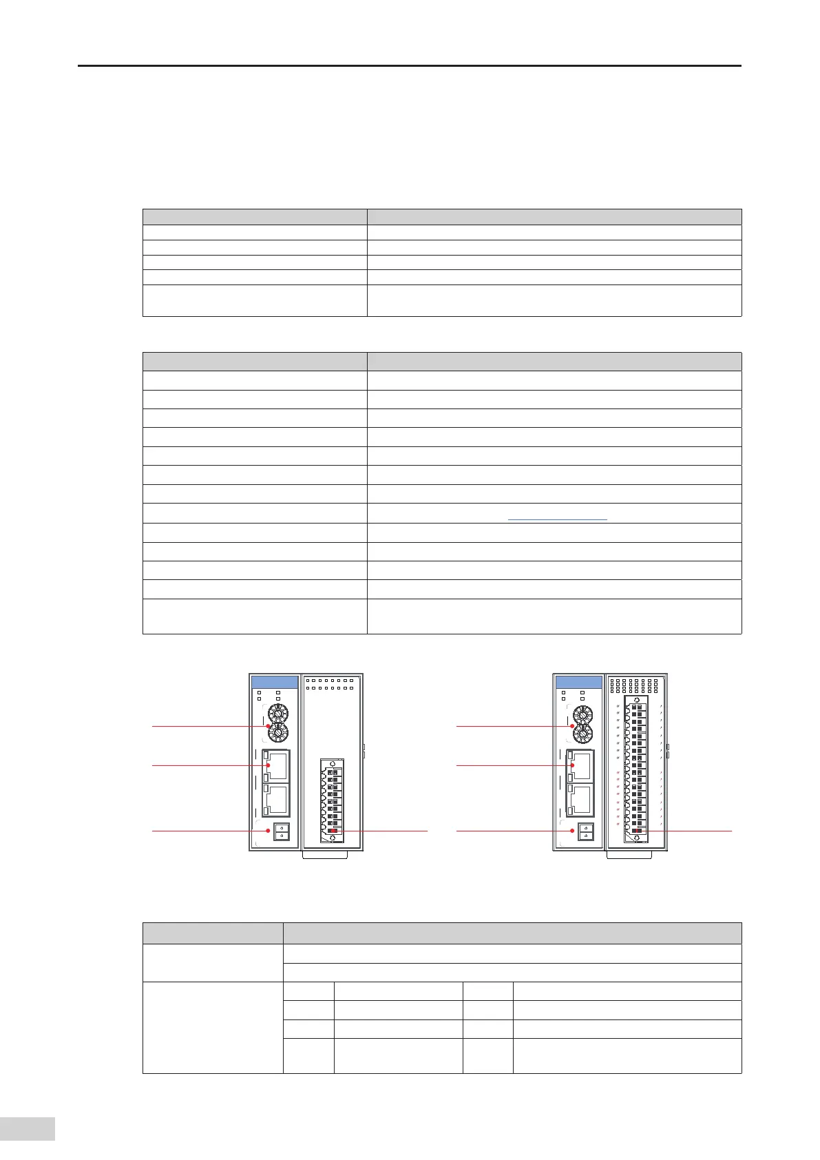
2) Module interface description
0 1 2 3 4 5 6 7
1 2 3 4 5 6 7
X
Y
X1 IN
X2 OUT
X1X16
0V 24V
PWR RUN
SF ERR
AM600-0808ETNE
0
X1
X3
X5
X7
Y0
Y2
Y4
Y6
COM
X0
X2
X4
X6
SS
Y1
Y3
Y5
Y7
EtherCAT
communication
port
Address switch
(rotary)
24 V power input
terminal
User output
terminal
EtherCAT
communication
port
Address switch
(rotary)
24 V power input
terminal
User output
terminal
Y0
Y1
Y2
Y3
Y4
Y5
Y6
Y7
X0
X1
X2
X3
X4
X5
X6
X7
X0
X1
X2
X3
X4
X5
X6
X7
SS0
Y0
Y1
Y2
Y3
Y4
Y5
Y6
Y7
COM
COM
SS1
0 1 2 3 4 5 6 7
1
2 3 4
5 6
7
1 2 3 4 5 6 7
1 2 3
4 5 6 7
X
X
Y
Y
X1 IN
X2 OUT
X1X16
0V 24V
PWR RUN
SF ERR
AM600-1616ETNE
0
0
0
Figure 3-25 Module interfaces
Interface Name Function
EtherCAT communication
port
X1 IN: EtherCAT input interface
X2 OUT: EtherCAT output interface that connects to the back-end EtherCAT slave station
Signal indicators
PWR Power indicator Green On when the power is switched on
RUN Running indicator Green On when the module is running normally
SF Module fault indicator Red On when the module is faulty
ERR
State machine error
indicator
Red On when a state machine error occurs
 Loading...


