-69-
Introduction
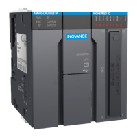
If you solder a PVC cable to the shield of the shielded cable and connect the front end of the cable to the
ground
,
the high-frequency impedance increases
,
weakening the shield eect. Therefore
,
this method is
not recommended.
4IJFMEFE
DBCMF
17$DBCMF
$SJNQUFSNJOBM
Figure 5-3 Shielded cable grounding requirement
Analog signal cables must be connected to the ground at one end close to the module. Shielded cables
of high-speed I/O
,
eldbus
,
and communication signals must be connected to the ground at both ends.
5.1.2 Wiring Requirements
Low-voltage cables (lower than 1 kV) are categorized into four types. Only cables of the same type can be
bound together. Cables of dierent types must be laid separately. If cable crossing cannot be avoided
,
use right-angle crossing.
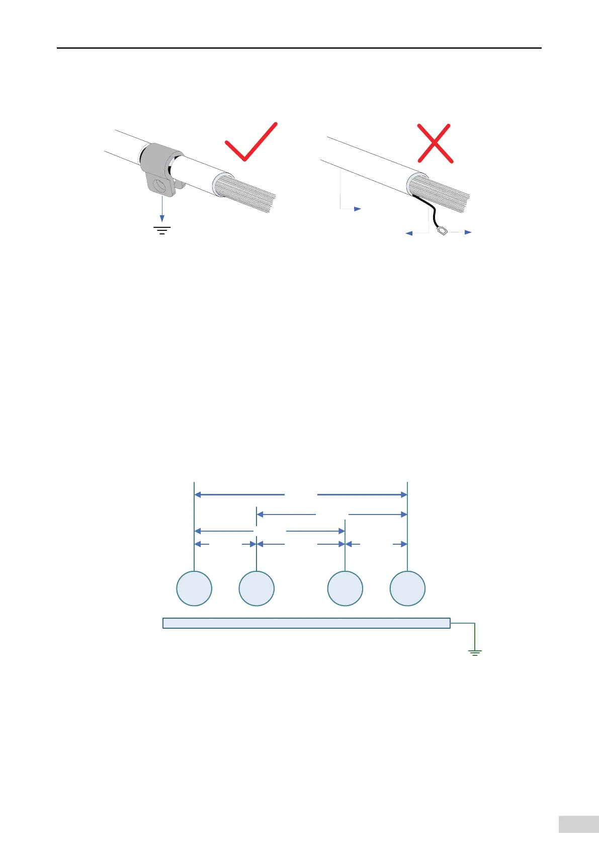
For cables shorter than 30 m
,
the allowable cable distance is shown in the following gure. You need to
increase the distance between cables with increase of parallelly-laid length of the cables. You can also
use shield plates assembled together between cables of dierent types to shield them from each other.
To reduce crossing interference
,
cables must be laid as close as possible to the structural components
connected to the cabinet ground
,
for example
,
the assembly plate and rack components of the cabinet.
5ZQF 5ZQF 5ZQF 5ZQF
NN NN NN
NN
NN
NN
Figure 5-4 Wiring requirements for dierent types of cables
[Note] Type 1: Ethernet and EtherCAT cables
Type 2: low-speed digital communication signal cables (for example
,
RS232
,
RS485
,
and CAN
signals) and digital I/O signal cables
Type 3: low-voltage AC distribution cables (for example
,
PLC 220 V AC power cables) and DC power
cables (for example
,
DC 24 V power output by the switching-mode power supply)
Type 4: input and output cables
,
welding machine cables
,
and power cables of power converters
 Loading...


