Intel is a registered trademark of Intel Corporation or its
subsidiaries in the United States and other countries.
*Other names and brands may be claimed as the property
of others. Copyright © 2012, Intel Corporation. All rights
reserved.
Warning
Read all caution and safety
statements in this document
before performing any of the
instructions. Also see the Intel
®
Server Board and Server Chassis
Safety Information document at:
http://www.intel.com/support/
motherboards/server/sb/cs-010770
.htm for complete safety information.
Warning
Installation and service of
this product should only be
performed by qualified service
personnel to avoid risk of injury from
electrical shock or energy hazard.
Caution
Observe normal ESD
[ElectroStatic Discharge]
procedures during system
integration to avoid possible
damage to server board and/or
other components.
1
Preparing the Chassis
If using a non-Intel
®
server chassis, refer to the documentation that came with your chassis for
preparatory steps.
Observe normal ESD (ElectroStatic Discharge) procedures.
Place your Intel
®
Server Chassis and Intel
®
Server Board on a
flat anti-static surface to perform the following integration procedures. Always touch the chassis
frame first, before reaching inside to install the server board, make server board connections, or
install other components.
Tools Required
Fastener Identification Guide
Anti-static
wrist strap
Phillips*
screwdriver
Flat-blade
screwdriver
Minimum Hardware Requirements
To avoid integration difficulties and possible board damage, your system must meet the
following minimum requirements:
• Memory Type: 32 GB maximum with x8 ECC UDIMM (2Gb DRAM).
• Power: Minimum of 350 W with 3A of standby current, which meets the SSI EPS 5V specification.
• Processor: Intel
®
Xeon
®
E3-1200 V3 processors or the 4
th
Generation Intel
®
Core™ i3 processors.
Labels on outside
face of I/O Shield
2
Installing the I/O Shield and Attach I/O Labels
Install the I/O Shield
Attach the Labels to the I/O Shield (optional)
Shield is installed from
inside the chassis.
The labels should be visible
from the outside of the
chassis.
Insert one side edge of
shield as shown.
Push shield firmly into
chassis opening until it
clicks into place.
B
A
Remove the backing from one of the three I/O
Shield labels included with your server board.
Press the label onto the I/O Shield as shown.
B
Repeat steps to install the second and third I/O Shield labels.
C
A
Intel
®
Server
Chassis P4000 series shown
Note: The I/O Shield and label installation procedures shown below apply to the
Intel
®
Server Chassis P4000S series.
Note: Make sure you install the labels on the correct
side of the I/O Shield. Note the orientation of the
cutouts in the drawing before attaching your labels.
Chassis Back
Panel Opening
B
A
4
Install the Server Board
B. Attach the Server Board
A. Insert the Server Board
Place the board into the chassis, making sure that the back panel I/O openings and
chassis standoffs align correctly.
Use screws to attach the board to the chassis at the eight locations indicated by the
solid blue arrows in the figure [ ].
The directions below are for the Intel
®
Server Chassis P4000S series.
For a non-Intel
®
server chassis, use the fasteners that came with your chassis.
• When using the Intel
®
Server Chassis P4000S series, insert the front of the board
first, then slide the board back so the I/O connectors fit through the I/O
openings at the rear of the chassis.
IMPORTANT NOTE:
If you are using a non-Intel
®
server chassis, see your
chassis documentation for preparatory steps prior to server board installation.
Intel
®
Server Chassis
P4000 series Shown
Intel
®
Server
Chassis P4000 series
Fastener
I/O Openings
Front edge
of Board
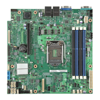
Thank you for buying the Intel® Server Board S1200V3RP Family Products.
The following information will help you integrate your new server board
into a server chassis. This document is using Intel® Server Board S1200V3RPL
with Intel® Server Chassis P4000 series as an assembly example.
Intel® Server Board S1200V3RP Family Products
Quick Start User's Guide
If you are not familiar with ESD (ElectroStatic Discharge) procedures used during system integration,
please see the Intel® Server Board S1200V3RP Service Guide, available on the Intel® Server Deployment
Toolkit DVD or at http://www.intel.com/p/en_US/support/server.
Please boot to the Intel® Server Deployment Toolkit DVD first for BIOS and firmware configuration and updates.
Read all cautions and warnings first before starting your server system integration.
When installing the server board into a reference chassis,
refer to the reference chassis instructions.
For details on these chassis or to select a third party chassis,
please visit http://www.intel.com/go/serverbuilder and
http://www.intel.com/p/en_US/support/server.
Install the Processor ...continued
Make sure the front edge of the load plate slides
under the shoulder screw as the lever is lowered.
F. Engage the Load Plate
A
Close the load plate locking lever.
B
Push down on the locking lever.
G. Latch the Locking Lever
A
Slide the tip of the lever under the
notch in the load plate. Make sure
the lever is securely latched.
B
H.
Remove the Cover
Carefully lift the cover
straight up as shown.
B
A
Load Plate
Front Edge
Shoulder
Screw
CAUTION: DO NOT damage the
server board with the tip of the
locking lever.
Save the
protective
cover.
A
E. Close the Load Plate
Carefully lower the load plate
over the processor.
A
A
B
5
Install the
Processor
A. Open the Socket Lever
Push the lever handle down
and away from the socket to
release it.
Rotate the lever
open all the way.
B. Open the Load Plate
Open the
load
plate as
shown.
A
B
Orient the processor with the socket so that the processor
cutouts match the two
socket pins.
A
Note the location
of the gold key
at the corner of
the processor.
B
C. Unpack the Processor
Cautions:
CAUTION: The underside of
the processor has components
that may damage the socket wires if
installed improperly.
Processor must align correctly with
the socket opening before installation.
DO NOT DROP processor into socket!
Components
When removing the protective
cover, DO NOT TOUCH the
gold socket wires.
A
When unpacking a processor,
hold by the edges only to avoid
touching the gold contact wires.
C
To avoid damage, DO NOT
DROP the cover onto the
socket wires or components.
B
C
Carefully remove
protective cover
as shown.
Save the
protective
cover.
A
B
D.
Install the Processor
Carefully lower the load plate
over the processor.
A
Note: Heatsink
styles may vary
2
3
1
4
TIM
A
E
6
Install Active Heatsink(s)
Use the following procedure to install an active heatsink
to your server board:
An active heatsink is required for the Intel
®
Entry Server Chassis
P4000 series. A typical active heatsink is shown at right.
Rotate the active heatsink so that the power connector can reach
the CPU fan header on the server board.
Make sure the screwdriver slot at the top
of each fastener is rotated perpendicular
to the blades of the heatsink as shown.
A
Align the heatsink to the holes
in the board and lower assembly
to the board. Snaps go through
holes in server board.
B
Press downward
on the top of the cap.
C
Plug the fan cable into the CPU fan header.
E
Fastener snaps
into final position.
D
Repeat B-D for each
fastener in the numerical
order shown at left.
CAUTION: The heatsink has thermal interface
material (TIM) on the underside of it. Take caution
not to damage the thermal interface material. Use
gloves to avoid injuries from sharp edges.
3
Install Server Board Bumpers
Prepare Server Board
Attach the Bumpers
Locate the four circles as shown.
B
Rotate board to show bottom-side
and hold upright as shown.
A
IMPORTANT NOTE:
If you are using a non-Intel
®
server chassis that includes bumpers, refer to
the chassis documentation for bumper installation. If you are using a non-Intel
®
server chassis
that does not include bumpers, consult with the chassis vendor to determine if bumpers are
required or not. If you are using an Intel
®
Server Chassis,
use the chassis bumpers that came with the chassis
.
CAUTION:
To avoid
damage to the server
board, do not lay flat with the
component side down.
Press a bumper onto each of
the four circles.
D
Remove the backing from each
bumper.
C
B
D
C
G83551-002