P/N 460802001C • REV 01.00 • 25JUL13 1
TruPortal
™
Dual Door
Interface Module
Quick Reference
en-US
Introduction
The TruPortal Dual Door Interface Module (TP-ADD-2D) can
support two complete door configurations, with up to two readers
per door. This module provides termination points for door
contacts (door position switches) and Request to Exit (RTE)
devices, as well as two door strike relays to control power to the
controlled access doors. It communicates with the TruPortal
System Controller (TP-SYS) via a two-wire RS-485 SNAPP bus.
Model Numbers
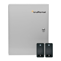
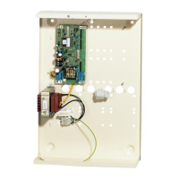
The TruPortal Dual Door Interface Module is available in a board-
only configuration (TP-ADD-2D-BRD) (see Figure 9) or pre-
installed in a UL or CE enclosure with or without bundled readers
and credentials (TP-ADD-2DR, TP-ADD-2D).
The TruPortal Dual Door Interface Module is available in the
following configurations:
• TP-ADD-2D-BRD (board only)
• TP-ADD-2D (installed in UL enclosure)
• TP-ADD-2D2R (installed in UL enclosure with two readers)
• TP-ADD-2D-E (installed in CE enclosure)
• TP-ADD-4D (installed in UL enclosure with two Dual Door
Interface Modules)
Note: -E model numbers are “Not Evaluated by UL” and
therefore cannot be used in UL installations.
Packing List
• TruPortal Dual Door Interface Module (quantity = 1)
• Mounting plate (depending on option ordered)
• UL or CE enclosure with power supply (depending on option
ordered)
• T-100 readers (depending on option ordered; quantity = 2)
• Installation kit which includes:
- Two positional terminal plug-in block (quantity = 5)
- Three positional terminal plug-in block (quantity = 4)
- Four positional terminal plug-in block (quantity = 4)
- Six positional terminal plug-in block (quantity = 2)
- 1N4005 diodes (quantity = 2)
- End-of-Line (EOL) resistors 1k ohm, 1% (quantity = 8)
- Plastic board supports for optional mounting
(quantity = 4)
Installation Procedure
To install the TruPortal Dual Door Interface Module, perform the
procedures described in the following sections, in the order in
which they are presented.
1. Mount the enclosure.
2. Mount the module in the enclosure.
3. Wire the relay outputs for door strike(s) and AUX.
4. Wire the reader(s).
5. Install the reader voltage jumpers.
6. Wire the alarm inputs.
7. Wire the tamper switch.
8. Wire the power and communications inputs
9. Apply power to the unit and listen for the relays to click.
Observe LED indicators to verify correct board operation.
10. Ensure all wires are clear and secure the cover.
WARNING: Circuit board components are vulnerable to damage
by electrostatic discharge (ESD). ESD can cause
immediate or subtle damage to sensitive electronic
parts. An electrostatic charge can build up on the
human body and then discharge when touching a
board. A discharge can be produced when walking
across a carpet and touching a board, for example.
Before handling any board, make sure to dissipate
any charge by touching the ground. This discharges
any static electricity build-up.