Electronic 4 - Circuit Astronomic
7 - Day Time Switch
Installation and Setup Instructions
With Supercapacitor Carryover
Federal Communications Commission (FCC) Notice for ET8415 Time Switch
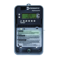
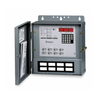
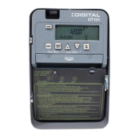
This document explains the setup and conguration of the Intermatic ET8415 4-Circuit Electronic Astronomic
7-Day Time Switch. The ET8415 time switch automatically switches loads to a preset weekly schedule. The time
switch can support up to 28 xed ON and 28 xed OFF events (56 total) and up to four Astro events. Each event
can be applied to any combination of circuits and days.
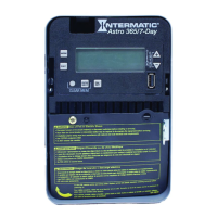
The time switch features an LCD and panel-mounted control buttons to set, review, and monitor the time switch
functions, including enabling or disabling Daylight Saving Time (DST) and conguring DST switchover dates.
Follow these instructions to complete the installation and programming for the ET8415 time switch.
Description
This device complies with part 15 of the FCC rules. Operation of this device is subject to the following two conditions: (1) This device may
not cause harmful interference, and (2) This device must accept any interference, including interference that may cause undesired opera-
tion. This equipment has been tested and found to comply with the limits for a Class A digital device, pursuant to Part 15 of the FCC Rules.
These limits are designed to provide reasonable protection against harmful interference when the equipment is operated in a commercial
environment. This equipment generates, uses and radiates radio frequency energy and, if not installed and used in accordance with instruc-
tions, may cause harmful interference to radio communications. Operation of this equipment in a residential area is likely to cause harmful
interference that requires the user to correct at his or her own expense.
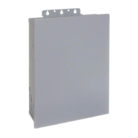
Installation
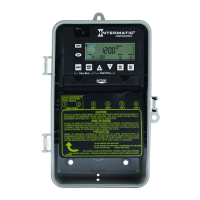
MODEL ET8415CR
NOTICE
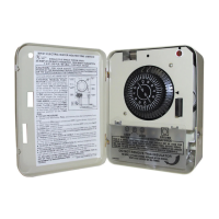
Follow these instructions to install the time switch.
1. Open the time switch enclosure door.
2. Press the catch at the top of the case and pull out the mechanism from the case.
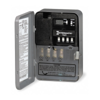
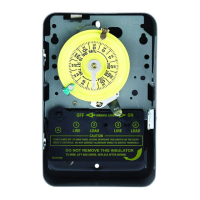
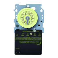
3. Choose a knockout to remove from the enclosure.
NOTE: There are five 1/2 inch to 3/4 inch combination knockouts available. There are
two on the bottom of the enclosure, one on each side, and one on the rear.
4. Insert a athead screwdriver into the slot of a 1/2 inch knockout and punch loose and
remove.
NOTE: If a 3/4 inch knockout is needed, remove the 1/2 inch knockout first, then the
outer ring. Smooth edge if necessary.
Snap out catch
Tilt top forward
Do not touch the circuit board components. Contact with the circuit board components can create static discharge, which can damage the
microprocessor.
Snap out catch
Tilt top forward
WARNING
Risk of Fire or Electric Shock
• Disconnect power at the circuit breaker(s) or disconnect switch(es) before installing or servicing.
• More than one circuit breaker or disconnect switch may be required to de-energize the equipment before servicing.
• Bonding between conduit connections is not automatic and must be provided as part of the installation.
• Installation and/or wire must be in accordance with National and Local Electrical Code requirements.
• Use #14 - #8 AWG wires, rated at least 90°C - COPPER conductors ONLY.
• If the power disconnect point is out of sight, lock it in the OFF position and tag it to prevent unexpected application power.
• Make sure there is not wire insulation under the terminal plate on the time switch connector. Firmly tighten terminal screws.
• Replace plastic insulator covering terminals before powering ON.
• KEEP DOOR CLOSED AT ALL TIMES when not servicing.