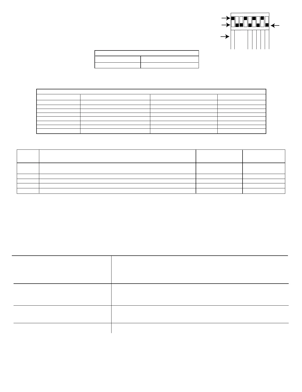
ADJUSTING DIP SWITCH SETTINGS
The occupancy sensor features 9 DIP switches. Each setting can be set to an up position or down position that
configures the DIP Switch setting to a specified requirement. Follow this procedure to adjust the DIP switch settings.
1. Adjust the sensitivity level DIP Switch (1). The Up position sets the sensitivity to 100%, while the down position
adjusts the sensitivity level to 50%.
DIP SWITCH 1 - SENSITIVITY LEVEL SETTINGS
50% Down position
100% Up Positions
2. Adjust the time delay DIP switches (2-4). Refer to the table for a list of the time delay options.
NOTE: After the sensor detects no motion in the coverage area, it will delay a user-configured amount of time before turning lights off. See the table before turning
lights off. See the table below to determine how to set the desired time delay for the sensor.
TIME DELAY SETTINGS
Time Delay 2 Switch Setting 3 Switch Setting 4 Switch Setting
15 Sec/Autoset Down Position Down Position Down Position
30 Seconds Down Position Down Position Up Position
5 Minutes Down Position Up Position Down Position
10 Minutes Down Position Up Position Up Position
15 Minutes Up Position Down Position Down Position
20 Minutes Up Position Down Position Up Position
25 Minutes Up Position Up Position Down Position
30 Minutes Up Position Up Position Up Position
3. Adjust Dip switch settings 5 through 9. See table 2 below for a description of each setting.
NOTE: For DIP switch settings 5 through 9, the up position enables the setting, while the down position disables the setting.
DIP
SWITCH Enable the Setting. Set Disable the Setting. Set
NUMBER DESCRIPTION DIP Switch To DIP Switch To
5 Walk Through - Turns the lights off for three minutes after the area is initially occupied. Up Position Down Position
If no motion is detected.
6 Vacancy - Turn this DIP switch to ON if you have a momentary switch. This enables overrides. Up Position Down Position
7 Audible Alert - An alarm (sounds like a tick) that indicates that the time delay has expired. Up Position Down Position
8 Visible Alert - An alarm (load LED flashes once) to indicate the time delay has expired. Up Position Down Position
9 Hold ON - Set this to ON to override all sensor functions Up Position Down Position
4. Install the front on the sensor and secure with the screws.
TESTING THE OCCUPANCY SENSORS
1. Ensure the PIR Activity is enabled Red LED flashes, Hold ON mode is OFF (DIP 9 switch OFF) and PIR Sensitivity is set to MAX (DIP switch 1 ON).
2. Make sure DIP Switches 2, 3, and 4 are set to the down (disable) position so the Time Delay is set for TEST MODE with the 15 seconds/AUTOSET setting.
3. Ensure the Light Level is the default (maximum).
4. Do not move so the sensor doesn’t detect the movement. The green LED and Load are ON and the lights should turn off after 15 seconds.
5. Move about the coverage area. The lights will illuminate.
6. When testing and adjustment is complete, reset DIP Switches and Light Level to the desired settings and replace the cover on the sensor.
NOTE: If you need to invoke the Test Mode and the DIP switches are already set for 15 seconds/Autoset, toggle DIP switch #3 ON the back to the OFF position. This
provides a 5-minute test period. During the test period, the Time Delay is only 15 seconds.
TROUBLESHOOTING
The PIR activity LED does not flash properly, The warm-up period has not been completed
Make sure the circuit breaker is on
Set the PIR sensitivity to Max/Autoset (DIP switch 1 ON)
Check all sensor and power pack connections
Check for 24V input to the sensor. If 24V is present, replace the sensor. If 24V is not present, check if the high
voltage is present to power pack. If it is, replace the power pack.
There is improper PIR activity, LED flashes Make sure the light level adjustment is set properly by covering the PIR lens and PIR activity LED to verify if lights
turn on. If lights still turn on, adjust the light level.
Check all sensor and power pack wire connections.
While the sensor is activated, check for 24 V DC at the blue wire connection at the sensor. If there is no voltage,
replace the sensor. If voltage is present, replace the power pack.
Lights do not turn on automatically Make sure the sensor is not experiencing activations from outside the controlled area
Check all sensor and power pack wire connections
Disconnect the blue wire. If lights do not turn off, replace power pack. If lights turn off, check the sensor.
Turn the sensitivity and time delay to minimum and allow the sensor to time out.
The sensor is activating without detecting movement Set the DIP switch 1 to OFF
Relocate the sensor.
158--02108REF
123
45
67
8
9
ON
1
2346
7
9
5
Sensitivity
Time
Delay
Walk-Through
Vacancy
Audible Alert
Visible Alert
HOLD ON
8
Up Position
Down Position
DIP SWITCH
DIP Switch
Settings
Settings Chart
LIMITED WARRANTY
Warranty service is available by either (a) returning the product to the dealer from whom the unit was purchased or (b) completing a warranty claim online at www.intermatic.com. This warranty is made by: Intermatic
Incorporated, 1950 Innovation Way, Suite 300, Libertyville, IL 60048. For additional product or warranty information go to: http://www.Intermatic.com or call 815-675-7000.
 Loading...