GENERAL INFORMATION 21
MAINTENANCE
1. VALVE CLEARANCE AND ADJUSTMENT
Note:
The cylinder head bolts were previously tightened with
the “Angular Tightening Method”. Therefore, it is not
necessary to retighten the cylinder head bolts before
adjusting the valve clearance.
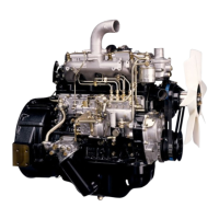
1. Bring the piston in either the No. 1 cylinder or the
No. 3 cylinder to Top Dead Center on the compres-
sion stroke by turning the crankshaft until the TDC
mark on the front cover aligns with the groove mark
on the crankshaft pulley.
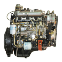
2. Check to see if there is play in the No. 1 intake and
exhaust valve rocker arms.
If the No. 1 cylinder intake and exhaust valve rocker
arms have play, the No. 1 piston is at TDC on the
compression stroke.
If the No. 1 cylinder intake and exhaust valve rocker
arms are depressed, the No. 4 piston is at TDC on
the compression stroke.
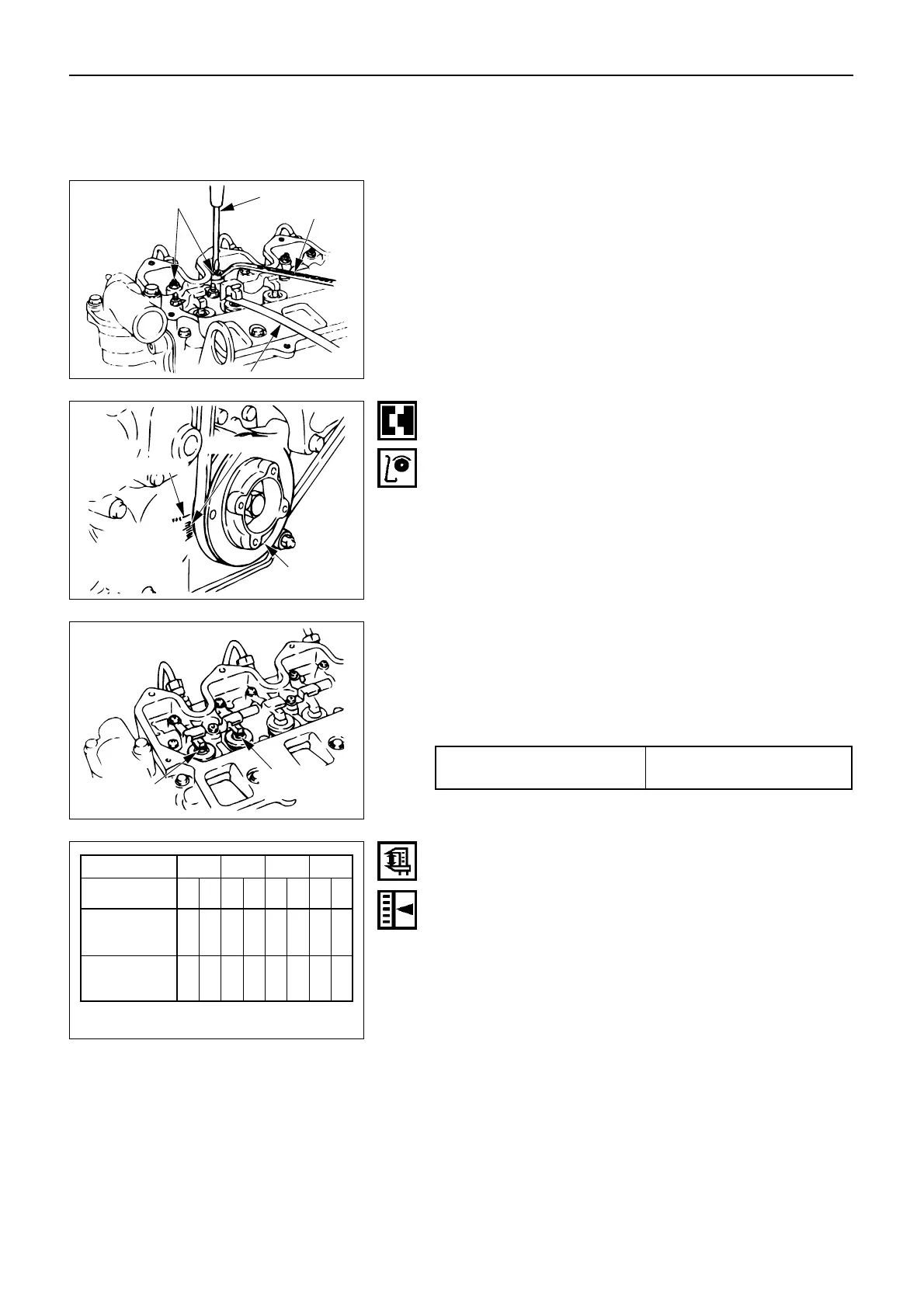
Adjust the circle or double circle marked valves as
shown in Fig. 24, while the No. 1 or the No.4 cylin-
der is at TDC on compression stroke.
mm (in.)
Intake and Exhaust
Valve Clearance (cold)
0.40 ± 0.05 (0.015 ± 0.002)
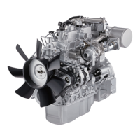
3. Loosen each valve clearance adjusting screw as
shown in the illustration.
4. Insert a 0.40 mm (0.015 in) feeler gauge between the
rocker arm and the valve stem end.
5. Turn the valve clearance adjusting screw until a
slight drag can be belt on the feeler gauge.
6. Tighten the lock nut securely.
7. Rotate the crankshaft 360°.
Realign the crankshaft pulley.
8. Adjust the clearances for the remaining valves as
shown in the illustration.
 Loading...