Quick Start
Copyright ©ITECH Electronic Co., Ltd. 10
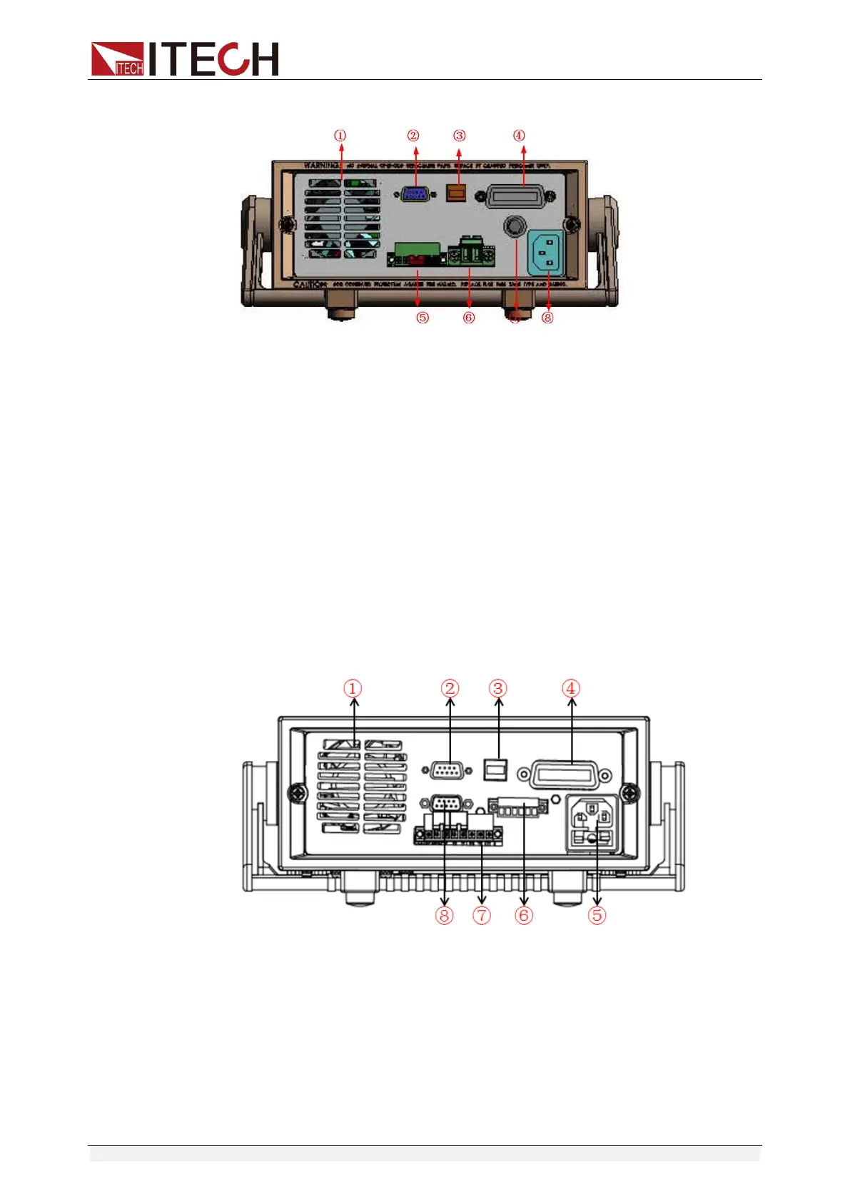
The rear panel of IT6952A/IT6953A is shown in the next figure.
1. Cooling window
2. RS232 Communication cable interface
3. USB Communication cable interface
4. GPIB Communication cable interface (IT6900(G) series only)
5. Remote measurement terminal and DVM input terminal
Attention: The + and - terminals here are only used for shorting
between S+ and S-, not the output terminals, so do not connect to
the DUT.
6. Output terminal
7. Fuse
8. AC power socket
The rear panel of IT6922B/IT6932B/IT6933B/IT6942B is shown in the next
figure.
1. Cooling window
2. RS232 Communication cable interface
3. USB Communication cable interface
4. GPIB Communication cable interface (IT6900(G) series only)
5. AC power socket (fuse contained)
6. Output Sync signal interface and RS485 Communication cable
interface
7. DVM input terminal, Remote measurement terminal and the output
terminal
 Loading...