The JA-116E / JA-116E-AN / JA-116E-GR
BUS touchscreen keypad with RFID reader
Typ: 1KPAD2203RN
JA-116E / JA-116E-AN / JA-116E-GR 1 / 3 MRN51603
The keypad is a component of the JABLOTRON system and is
designed to be operated by touch. The keypad must be installed by
a trained technician with a valid Jablotron certificate issued by an
authorised distributor. This product is compatible with JA-103K
and JA-107K control panels.
This manual must be used together with the installation and
user manual of the JABLOTRON control panel system.
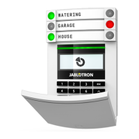
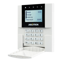
The keypad components are shown in the following figures:
Figure 1 – front part: 1 – touchscreen; 2 – button/system indicator;
3 – RFID reader – reading area
Figure 2 – internal part: 4 – connection points of the BUS terminal;
5 – serial number; 6 – tamper contacts; 7 – USB-C connector;
8 – locking mechanism; 9 – rear part tab
Figure 3 – mounting pad: 10 – BUS terminal
Installation
1. Remove the mounting pad (Fig. 3) of the keypad. If it cannot be
r
emoved easily, open the locking mechanism, see chapter “Keypad
disassembly”.
2. In the mounting pad, break out the blank of appropriate slot, pull
the BUS cable through, and then screw the mounting pad of the
keypad to the designated place, preferably on a solid base (wall).
Select the installation height of the keypad with respect to the
height of the users. The ideal height for good readability and
control is at eye level. It is not recommended to mount at a height
consistent with electrical switches (100-110 cm).
3. Connect the individual wires of the BUS cable to the BUS
terminal (10) as follows:
a) Using a flat screwdriver to press upper side of the terminal.
b) Put a stripped wire into the appropriate terminal.
c) Release the terminal.
d) Test if the wire is correctly fixed with a gentle pull.
+U
– red; positive power supply pole
A – yellow; data wire A
B – green; data wire B
GND – black; negative power supply pole
Notes:
− Connect only straight, stripped wires to the BUS terminals
(their ends only).
− Use a narrow flat screwdriver to turn the locking mechanism
and release the tab.
Always switch the power
connecting the keypad to the BUS.
4. First, attach the bottom edge of the keypad to the mounting pad
(align the bottom sides) and slide in downwards until you hear the
click of the tab (9). This will secure the keypad against falling out of
the mounting pad. Then turn the locking mechanism (8) clockwise
90° to the position where the groove points to the symbol . This
locks the keypad in place and engages the tamper contact.
5. Power the system on.
6. Enrol the keypad to the system according to the type of control
panel, use the recommended software or application, see the
installation manual of the control panel.
Notes:
− Enrolment is possible by entering the serial number (5) in the
F-Link software or appropriate application. All numbers stated
under the bar code must be entered (1400-00-0000-0001).
− Another enrolment option is using F-Link software, within th
e
D
evices tab -> Scan/Add new BUS devices; or by pressing the
button (2).
Keypad disassembly
On the underside of the keypad, turn the locking mechanism (8)
counterclockwise 90° until the groove points to the symbol . Insert
the flat screwdriver into the tab hole (9) (push the screwdriver
towards the wall) while sliding the keypad upwards. The keypad can
then be easily removed from the mounting pad.
Authorisation – can be done by entering a valid access code on
the virtual keypad or by applying the access card / chip. Authorization
will terminate itself after 15 seconds from the last detected touch on
the screen, or immediately by pressing the button (2), or it can be
terminated by the logout icon in the upper left corner. The individual
keypad screens and menus and the system control options are
based on the user access rights configured in the control panel.
JABLOTRON ALARMS a.s.
Pod Skalkou 4567/33 46601 Jablonec n. Nisou
Czech Republic www.jablotron.com
||
|