Cassette/CD Tuner
CD Player
or Changer
CD Input
Cassette/CD Preamp Output
Antenna Input
Power
Antenna
Power
Antenna
Relay
Blue w/White Stripe - Remote On/Off
Main +12V
Power Ground
Chassis Ground
Vehicle Battery
–
+
Ignition Switch
Antenna
Motor
Power
Supply
Blue (Blue/White)
Remote On/Off
Remote Antenna
Black - Power Ground
Red - Main +12V
Yellow - Back Up Power
Fuse
Fuse
Fuse
Cassette/Receiver
Power Supply
Wires
Speakers
+
–
+
Speakers
+
–
+
(Not Included)
Amplifier
Power
Connection
Amplifier
Speaker
Output
Connection
Amplifier
Speaker
Output
Connection
Amplifier
Speaker
Output
Connection
Amplifier
Speaker
Level
Inputs
Cassette/CD Tuner
Speaker-Level Output Connection
(Use only when line-level output
is not available)
draws negligible current so a relatively
small (18 or 20 gauge) wire may be used.
• Using the REM-OUT feature – The REM-
IN/OUT terminal of the GTQ amplifier
may be used to turn on other amplifiers
when the GTQ amplifier is being turned
on by the Common Sense circuitry in the
speaker-level input. Simply connect the
head unit speaker-level outputs to the
GTQ amplifier speaker-level inputs and
connect the REM-IN/OUT terminal to the
remote-in terminal of other amplifiers or
signal processors. The GTQ amplifier will
turn on the other amps or processors
whenever the Common Sense circuitry
turns on the GTQ amplifier.
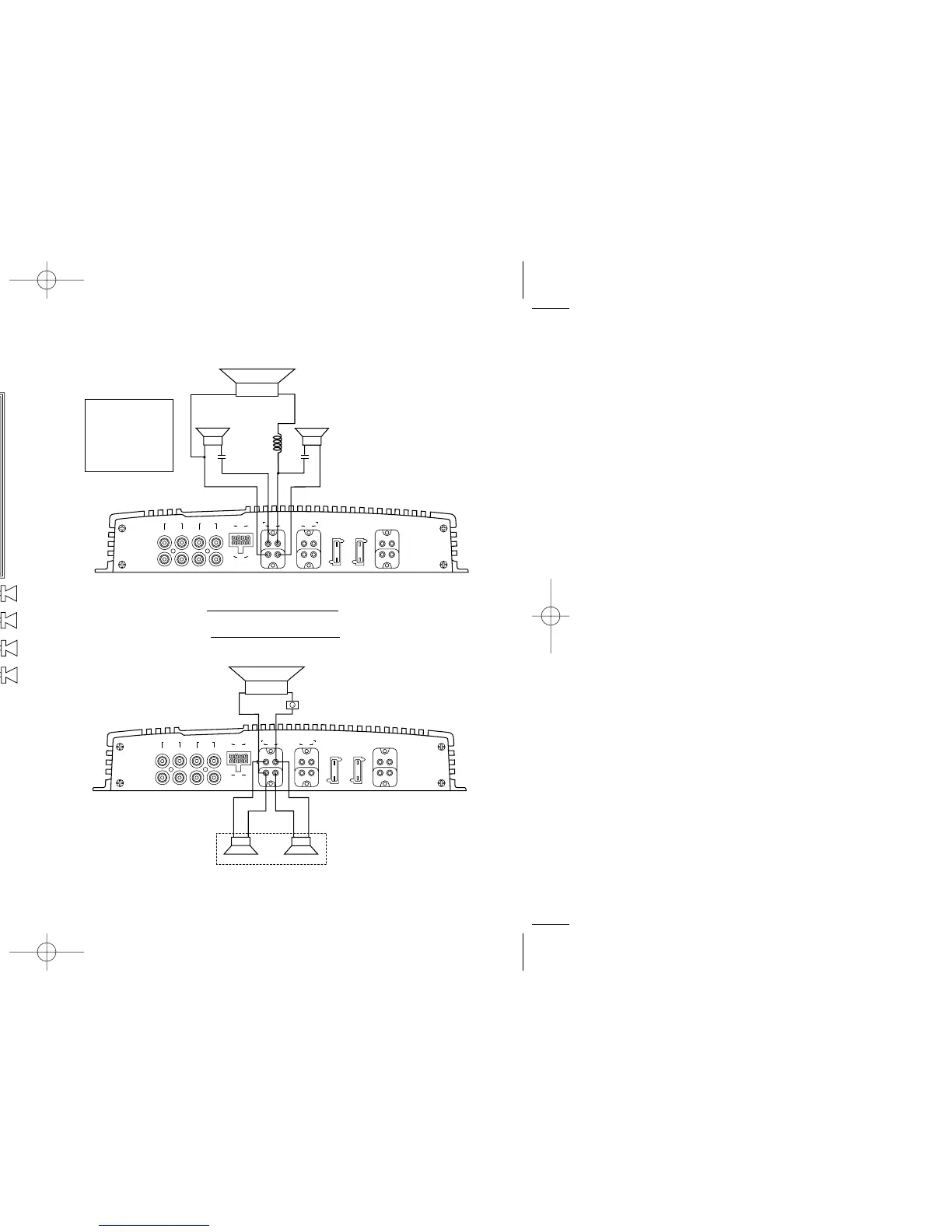
High-Pass Satellite
Crossover Frequency: 100Hz
C: 300µF capacitor
100V, non-polarized
Subwoofer Low-Pass
Crossover Frequency: 100Hz
L: 6.2mH air core inductor
(+)
(+)
(–)
(–)
(+)
(–)
C
Subwoofer (Low-Pass)
Tweeter/Midrange Satellites
(High-Pass)
Right
Left
C
L
GTQ360
A. Satellite/Subwoofer
Stereo, Non-Bridged
Speaker Connection*
Center Channel
Bridged Speaker Connection*
* Center Channel Speaker Minimum 8 Ohms, Main
Speakers Minimum 4 Ohms When Used Simultaneously.
8 Ω L-Pad
(Optional but Recommended)
4Ω Minimum 4Ω Minimum
GTQ360
(+)
(–)
(+) (+)
(–) (–)
8 Ω Minimum
B. Center Channel
*You may change the subwoofer satellite crossover frequency by using the
Inductor and Capacitor values calculated with the following formulas:
High-Pass (Satellite Crossover): = New Capacitor Value in µF
Low-Pass (Subwoofer Crossover): = New Inductor Value in mH
30,000
Desired crossover Frequency in Hz
620
Desired crossover Frequency in Hz
30A
30A
GR1
R GR1 L
LINE LEVEL
INPUT
SPEAKER LEVEL INPUTS SPEAKER OUTPUTS (BRIDGED: R
+
TOL
–
)
POWER
GR2 GR1 GR2
BATT(+) GND
MUTE
FUSE
30A
FUSE
30A
REM
IN/OUT
L
+– –+
+– –+ + +
––––
R
PREAMP
OUTPUTS
R GR2 L L GR1 R
++
L GR2 R
30A
30A
GR1
R GR1 L
LINE LEVEL
INPUT
SPEAKER LEVEL INPUTS SPEAKER OUTPUTS (BRIDGED: R
+
TOL
–
)
POWER
GR2 GR1 GR2
BATT(+) GND
MUTE
FUSE
30A
FUSE
30A
REM
IN/OUT
L
+– –+
+– –+ + +
––––
R
PREAMP
OUTPUTS
R GR2 L L GR1 R
++
L GR2 R
Simultaneous Stereo-Mono Connection Diagrams
GTQ 360 new 7/17/98 10:44 AM Page 6
 Loading...