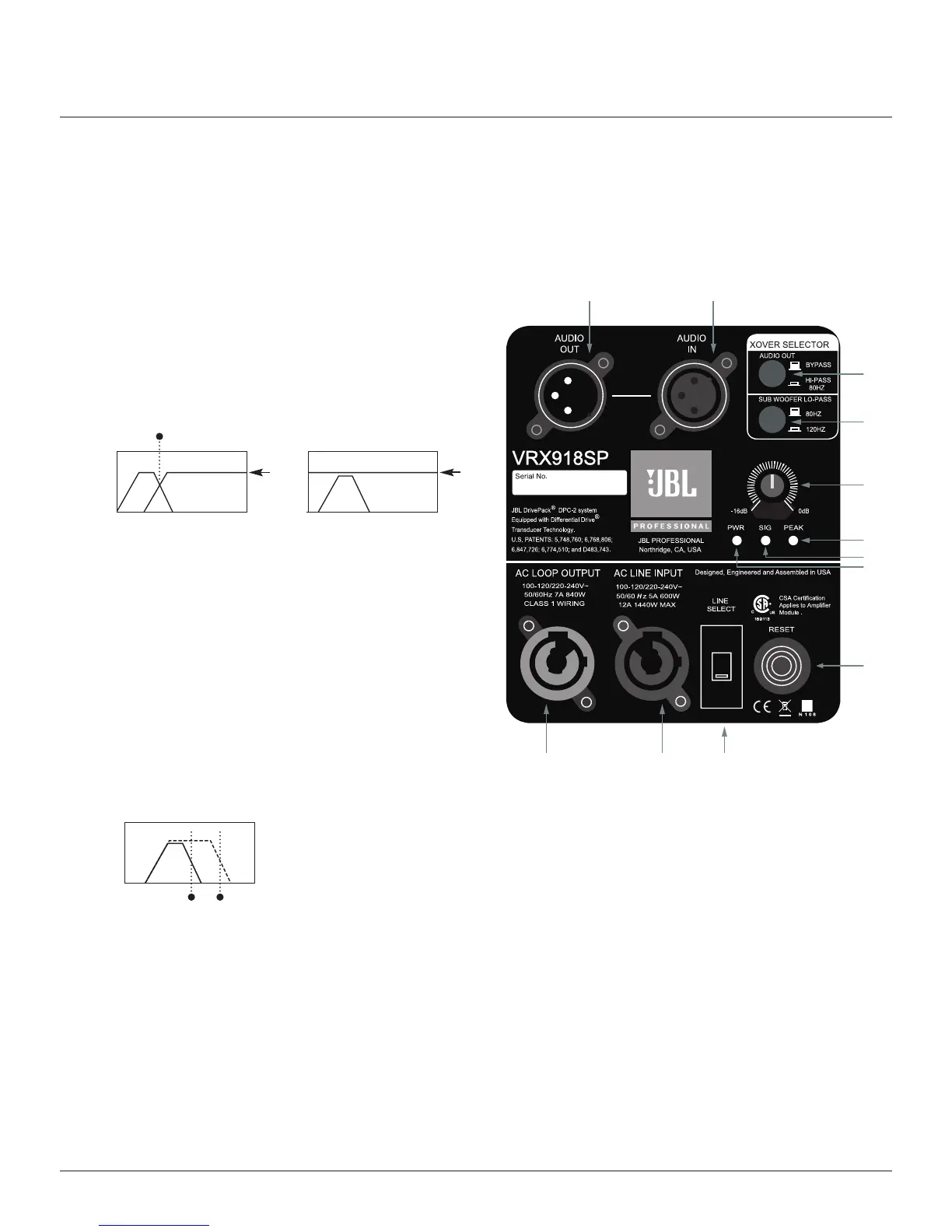
The VRX918SP input panel features analog audio inputs and sophisticated onboard digital signal processing
technology. Precision Bandpass limiting and automatic self-protection functions ensure maximum performance.
CONTROLS
1. AUDIO OUT
Two-position push-button DSP preset selection switch,
enables an 80Hz Hi-Pass filter (graph 1) or direct loop
through (graph 2) to the audio output. When set to the
“Hi-Pass 80Hz” position, the signal leading to the
AUIDIO OUT connector is shaped in such a way (graph 1)
that allows a smooth transition to a connected full range
speaker, crossed over at 80Hz.
(The Hi-Pass frequency is fixed at 80Hz)
When connecting to a second VRX918SP sub woofer
set the switch of the first subwoofer to bypass and the
last subwoofer to Hi-Pass, so that the last subwoofer
in the signal chain provides the xover to the full range
system.
2. SUB WOOFER LO-PASS
Two-position push button DSP preset selection switch,
engages either an 80Hz or 120Hz Lo-Pass filter (graph 3).
The default 80Hz position is recommended. The120Hz
Lo-Pass filter option becomes useful when external
signal processing is used or if the low frequency extension
of the companion full range system does not reach 80Hz
3. ATTENUATION
Detented rotary input sensitivity control attenuates level in 0.5 dB steps. The Input Sensitivity is +4 dBU
nominal (+20 dBU clip) with the control fully counter clockwise, and -10 dBV nominal (+4 dBU clip) with
the control fully clockwise. (Note: Professional mixing boards with XLR outputs should use the fully counter-
clockwise position as a starting point. Whereas semi-professional equipment with 1.4 inch jack’s, RCA
connectors and unbalanced sources should start at the middle position - watch for clipping (peak LED)!
4. RESET
Press to reset line voltage circuit breaker.
5. LINE SELECT
Two-position slide switch, set to 115V position for (100-120V~) or 230V position for (220-240V~) operation.
1
2
3
6
7
8
4
51112
9
10
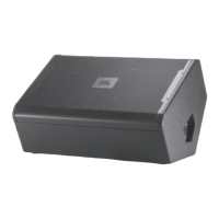
VRX918SP INPUT PANEL
graph 1
graph 3
17
80Hz
80Hz
120Hz
graph 2
Audio
Out
Audio
Out
 Loading...