10 TEC1100 Series Thermostat Technical Bulletin
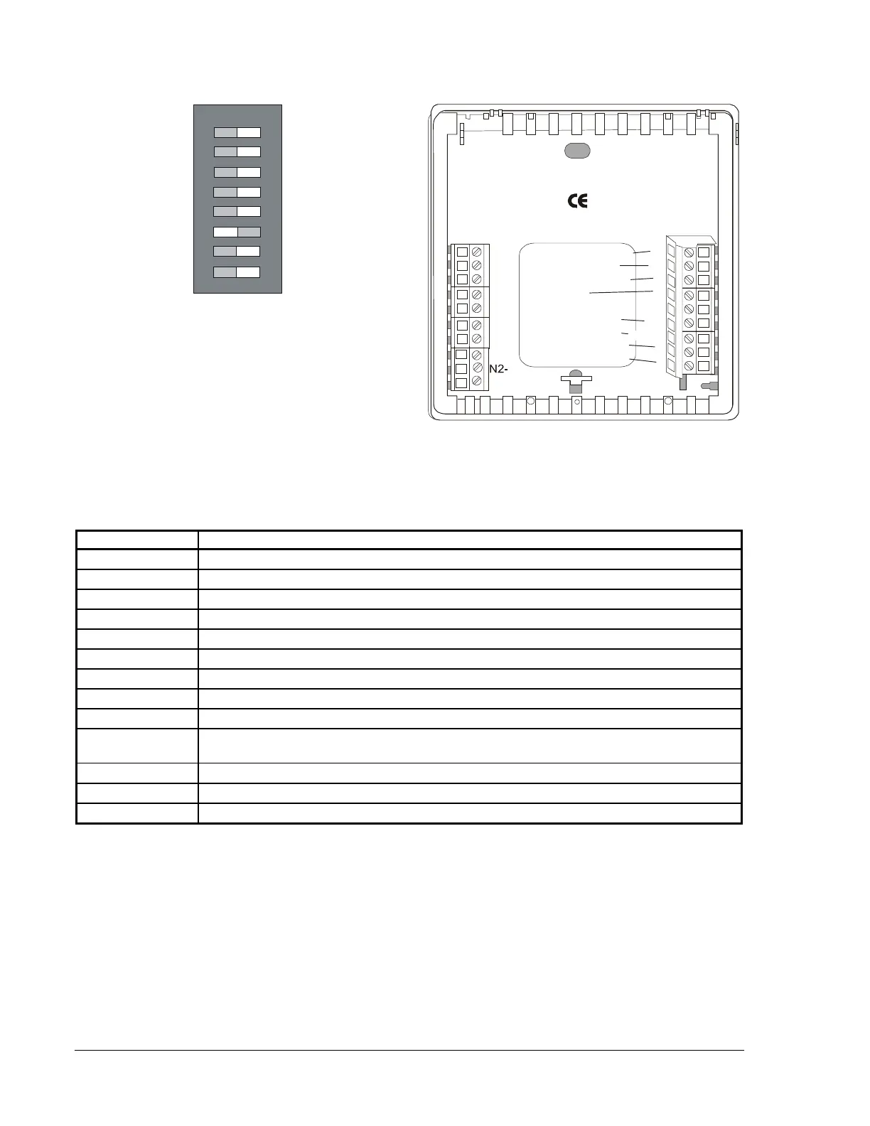
Economy
Single-Stage
LED 1 Icon Off
LED 2 Icon Off
Compressor/Auxiliary
Normal
Not Used
Heat/Cool: 4 Minute
(Minimum On/Off)
Keyboard Unlocked
ON
1
3
2
4
5
6
Compressor/Auxiliary
Interlocked
Not Used
Heat/Cool: 2 Minute
(Minimum On/Off)
Keyboard Locked
7
8
LED 1 Icon
(Filter)
LED 2 Icon
(Wrench/Fault)
Comfort
Multistage
LED1
LED2
CLK1
TEC1102
2nd Sta
e Compressor
Auxiliary Heating
1st Sta
e Compressor
Fan
Cool Reversin
Valve
Heat Reversin
Valve
Hpn2wire
N2+
N2 REF
Rs1
RS+V
CLK2
RS2
24 VAC Power In
24 VAC Common
Y2
W1
G
R
24V
24V(C)
Y1
O
B
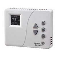
Figure 5: TEC1102 Heat Pump, Factory-Set DIP Switch Settings,
and Wiring Configuration
Table 8: TEC1102 Heat Pump Output Terminal Designations
Terminal Function
Y2
Energizes Compressor 2 on call for second stage heating or cooling.
W1
Energizes auxiliary heat as third stage heating or emergency heat.
Y1
Energizes Compressor 1 on call for first stage heating or cooling.
G Energizes fan on call for heating or cooling or by pressing Fan button.
R
Provides independent switching voltage.
24V
Provides 24 VAC from equipment transformer.
24V(c)
Provides 24 VAC (common) from equipment transformer.
LED 1, LED 2
LED 1 or LED 2 contact closure to 24 VAC from remote switch.
CLK1, CLK2
Connects remote clock/timer for alternate setpoints.
RS2, RS1, RS+V
Connects outdoor air temperature or indoor remote sensors; refer to instructions included
with sensors.
O
Energizes reversing valve in the Cooling mode.
B
Energizes reversing valve in the Heating mode.
N2+, N2-, Ref
N2 Bus