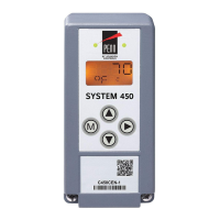
System 450™ Series Control Module with Ethernet Communications Installation
Instructions
1
Refer to the QuickLIT website for the most up-to-date version of this document.
Application
System 450™ is a family of modular, digital electronic
controls that is easily assembled and set up to provide
reliable temperature, pressure, and humidity control for
a wide variety of HVACR and commercial and industrial
process applications.
The System 450 control modules allow you to
configure custom application-specific control systems
with up to three input sensors and ten (relay or analog)
outputs, including control systems that can monitor and
control temperature, pressure, and humidity
applications simultaneously.
C450CEN-x control modules feature an LCD and
four-button touch pad UI that allows you to set up a
System 450 control system, and an RJ45 Ethernet
network port that enables you to connect your control
system to and communicate across an Ethernet
network.
The System 450 control module with Ethernet
communications has an integral web server that
supports browser access. The web server can be
configured to deliver System 450 web pages to client
browsers and allows you to monitor your control
system status and change your control system
configuration in simple, user-friendly web pages.
Refer to the System 450 Series Control Systems with
Network Communications Technical Bulletin
(LIT-12011826) for detailed information on designing,
installing, setting up, and troubleshooting System 450
Series control systems with network communications.
The technical bulletin can be accessed and
downloaded on the Johnson Controls® Online Product
Literature website at the following web address:
http://cgproducts.johnsoncontrols.com/default.aspx
System 450 control modules with network
communications also include the High Input-Signal
Selection, Differential Control, Output Signal Update
Rate, and Output Signal Dead Band features.
Installation
IMPORTANT: Use this System 450™ Series
Control Module only as an operating control. Where
failure or malfunction of the System 450 control
module could lead to personal injury or property
damage to the controlled equipment or other
property, additional precautions must be designed
into the control system. Incorporate and maintain
other devices, such as supervisory or alarm systems
or safety or limit controls, intended to warn of or
protect against failure or malfunction of the
System 450 control module.
Figure 1: System 450 Module
Dimensions, mm (in.)
63
(2-1/2)
FIG:new_enclosure_dims
1/2 in. Conduit Hole
(Nominal Trade Size)
35 mm
DIN Rail
Mount
Channel
63
(2-1/2)
63
(2-1/2)
40
(1-9/16)
40
(1-9/16)
(2-15/16)
System 450™ Series Control Module with Ethernet
Communications
Installation Instructions
C450CEN-x
Part No. 24-7664-2934, Rev. C
Issued December 6, 2013
Supersedes November 22, 2013

 Loading...