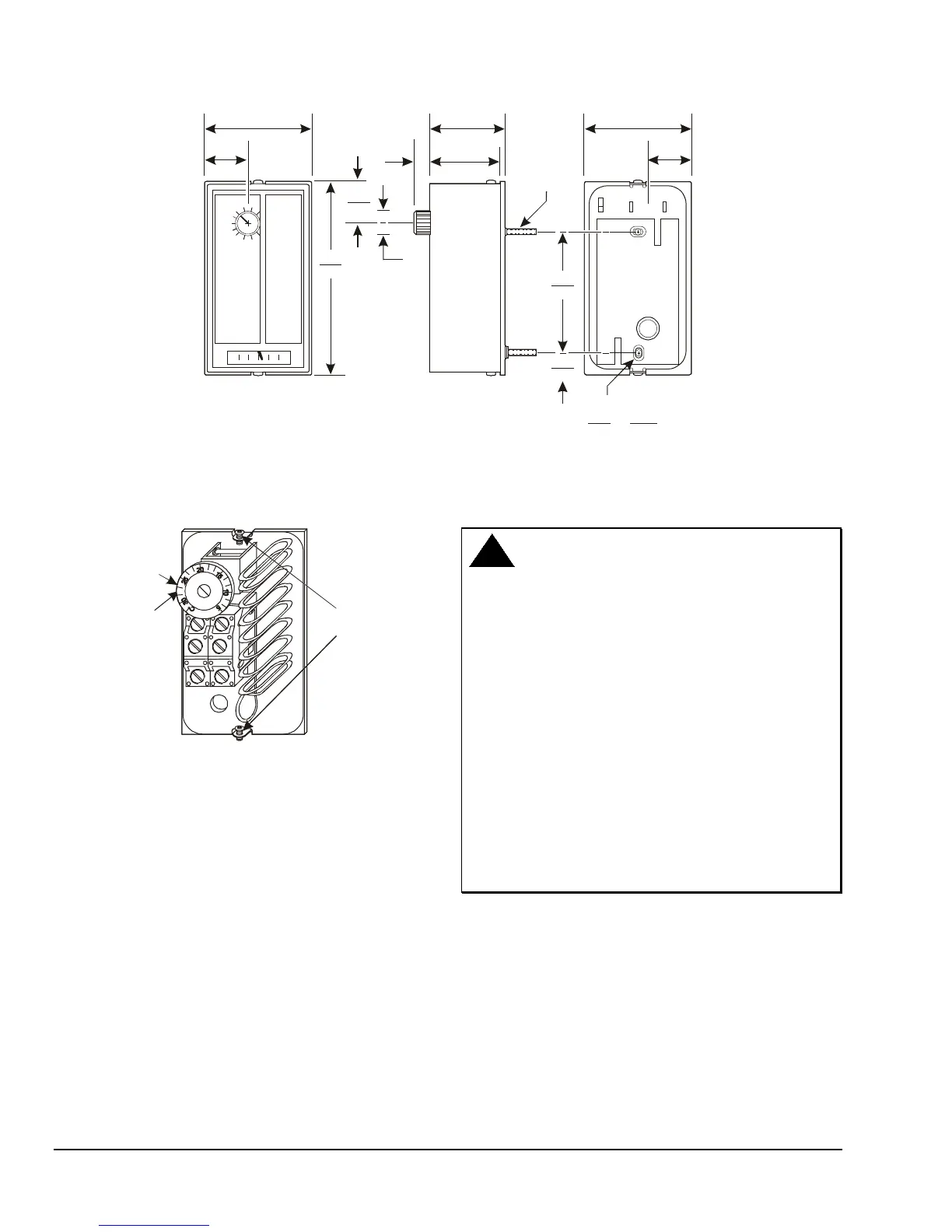
2.78
(71)
1.13
(29)
5.22
(133)
0.63
(16)
Diameter
1.06
(27)
1.94
(49)
1.88
(48)
0.41
(10)
Two Threaded
Studs
3.28
(83)
0.63
(16)
Two Mounting Holes
0.28
(7.1)
0.15
(3.8)
x
2.84
(72)
1.44
(37)
Figure 1: T25A Dimensions, in. (mm)
Mounting
Plate
Studs
High
Temperature
Stop
Set Point
Knob
Figure 2: Inside View of T25
Wall Box Mounting
To mount the thermostat to an electrical conduit box,
proceed as follows:
1. Remove the external adjustment knob, when
furnished, by loosening the knob set screw using
the provided Allen wrench. Slide the knob from the
adjustment shaft.
2. Remove the cover by loosening the Allen-head
screws at the top and bottom of the thermostat.
3. Remove the adaptor plate from the back of the
thermostat by loosening the machine nuts (inside
the thermostat) from the two threaded studs on the
plate.
WARNING: Risk of Electric Shock.
Disconnect or isolate all power supplies before
making electrical connections. More than one
disconnection or isolation may be required to
completely de-energize equipment. Contact with
components carrying hazardous voltage can cause
electric shock and may result in severe personal
injury or death.
AVERTISSEMENT : Risque de décharge
électrique. Débrancher ou isoler toute alimentation
avant de réaliser un branchement électrique.
Plusieurs isolations et débranchements sont
peut-être nécessaires pour -couper entièrement
l'alimentation de l'équipement. Tout contact avec
des composants conducteurs de tensions
dangereuses risque d'entraîner une décharge
électrique et de provoquer des blessures graves,
voire mortelles.
4. Pull the electrical thermostat wires through the
opening in the thermostat adaptor plate.
5. Secure the adaptor plate to the conduit box with
the two machine screws provided.
6. Insert the wires through the opening in the
thermostat base.
7. Place the thermostat on the adaptor plate, so that
the two threaded studs on the adaptor plate pass
through the corresponding holes in the thermostat
base (upper left and lower right corners).
2 T25 Two-Stage Room Thermostat Installation Instructions
 Loading...