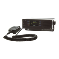
4.4 InstallaƟon of TR-910
4.4.8 Antenna connecon
The antenna should be of good quality with regards to gain and VSWR to obtain maximum performance.
Make sure that the VSWR on the antenna is low, and that the cable from the transmier to the antenna is
of good quality to avoid mismatch and unnecessary losses. A cable loss of 1 dB is the same as reducing the
power output of a 10 W transmier to less than 8.5 W. Similarly, a cable loss of 2 dB is the same as reducing
the output power to less than 7 W. In areas were thunderstorms and lightning are a problem, surge arrestors
should be mounted between the antenna connector and the antenna cable. The arrestors should be good
quality and be capable of handling the output power of the transmier. The antenna input of the transceiver
is the BNC-type antenna connector on the back of the transceiver unit.
Electrical Safety Earthing:
In case of installaon to external antenna, the antenna ground terminal must
be permanently connected/verified with protecve earthing conductor to
the building earth by a skilled person.
4.4.9 DC supply connecon
If the unit is to be installed in a vehicle, the included fuse kit (103079) in the vehicle variant accessory kit shall
be installed on the posive supply wire nearest the vehicle baery.
4.4.10 LAN connecon
If the unit is to be connected to a local area network, this can be done by connecng a standard RJ45 patch
cable from the LAN connector to the network switch or router. Using LAN enables remote monitoring by the
Jotron RCMS system, remote VoIP recording and remote control with VoIP according to ED137.
4.4.11 I/O connecon
Connect to the I/O connector preferably with the radio turned off.
The following remote signals are available on the rear I/O connector:
• External speaker (Pin1&2)output line pair is for connecng an external speaker. This speaker output
has a dedicated amplifier and the volume can be regulated independently from the internal speaker.
Note: Ensure that the external speaker signals are not short circuit to ground or to each other.
• Monitor output (Pin 3) is an analog monitor output, 600 Ω single ended and referenced to ground, pin
8. This output can for instance be used for connecng an analog recorder. It will contain the received
audio when receiving and the demodulated transmied signal when transming.
• TxKey / GPIO (Pin 4) is used to force the transmier into low power. This is oen used offshore to force
the unit into low power during gas alarm condions. This pin can also be configured to have other
funcons, e.g. Tx key input.
•Baery communicaon interface (Pin 5) is the communicaon line between TR-910 and the BU-872
baery pack. TR-910 uses this interface to read the baery status from the baery unit and present this
with a baery indicator on the front panel.
Doc. No.: 103614 TR-910 Operator Rev. AB jotron.com 37

 Loading...