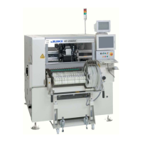
Maintenance Guide
viii
[16] FEEDER POSITION INDICATOR .................................................... 16-1
16-1. Detaching the FPI (Front) from the Machine Main Unit .................................... 16-1
16-2. Detaching the FPI (Rear) .................................................................................. 16-2
[17] PLACEMENT MONITOR (OPTIONAL) ........................................... 17-1
17-1. Replacing the LNC61/62................................................................................... 17-1
17-2. Replacing the EPV61/62................................................................................... 17-2
17-3. Replacing the Head Up Cylinder (KE-2080/2080R) .......................................... 17-3
17-4. Obtaining the Offset after Replacement ........................................................... 17-5
17-5. Checking the Images after Replacement .......................................................... 17-6
17-5-1. Calibration Application ..................................................................................................... 17-6
17-5-2. EPV Calibration ............................................................................................................... 17-9
[18] CVS (OPTIONAL) ........................................................................... 18-1
18-1. Replacing the CONTACT SUB UNIT ................................................................ 18-1
18-2. Replacing the PCB ........................................................................................... 18-4
[19] IS (OPTIONAL) ............................................................................... 19-1
19-1. Replacing the MPC and HUB ........................................................................... 19-1
19-1-1. HUB BOX Attached outside Machine .............................................................................. 19-1
19-1-2. HUB BOX Attached inside Machine ................................................................................ 19-4
19-2. Replacing the Cable and Connector of Collective Exchange Carriage ............. 19-9
19-3. Replacing the Antenna of Collective Exchange Carriage ............................... 19-10
[20] Traceability /On-demand (OPTIONAL) .......................................... 20-1
20-1. Replacing the RS-232C Port Expansion Board ................................................ 20-1
20-2. To replace the barcode reader: ........................................................................ 20-2
[21] JIG LISTS ........................................................................................ 21-1
21-1. KE-1070/1070C Jig Lists .................................................................................. 21-1
21-2. KE-1080/2070/2080/2080R Jig Lists ................................................................ 21-3
Appendix
1. Checking the Board Function Rev., Board Pattern Rev., and DIP SW ..................... A-1
2. Checking the Board Rev. on the Mounter Main Unit
(For KE-1070/70C/2070/80/80R) ....................................................................... A-2

 Loading...