Maintenance Guide
2-11
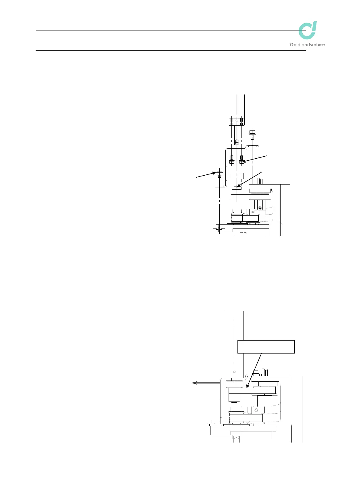
2-2-5. T-Motor (IC Head: KE-2080R)
After the T-motor has been replaced, it is absolutely necessary to re-input the MS parameters
related to the axis home. (For details of input items, see section 2-9.)
(1) Disconnect the motor cables from the servo
amplifier board.
(2) Remove the mounting screws c (3 pcs.) of
the IC T-motor bracket.
(3) Loosen the set screws (2 pcs.) of the IC
T-pulley to detach the pulley.
(4) Remove the mounting screws e (3 pcs.) from
the IC T-motor bracket to detach the motor.
(5) Reassemble the components in the reverse
order of disassembly.
Apply Loctite 242 to the mounting screws
e and tighten them with a tightening
torque of 2.3 N㺃m.
Make the adjustment so that the end face
of the motor shaft is aligned with the end
face of the pulley, and then fix the set screws of the T-pulley.
(6) Follow the steps below to adjust the belt tension.
<Procedure>
c Pull the IC T-motor bracket to adjust the
tension of the timing belt to the status shown
below.
Tension meter set value (For check)
Weight: 1.0g/m Width: 6.0mm
Span: 30.8mm
Proper tension 9.0±1N
When tightening the set screw of the T
pulley, make sure to align the orientation
of the flat part of the T-motor shaft and the
setscrew of the pulley. Tighten the
setscrew with a torque of 0.5 Nm.
Pull
IC Timing belt T
Figure 2-2-5
d
e
c

 Loading...


