– 107 –
2) Details of connectors
This clause explains details of connectors
①
to
⑤
,
⑤
-1
and layout of the pins shown in the wiring dia-
gram.
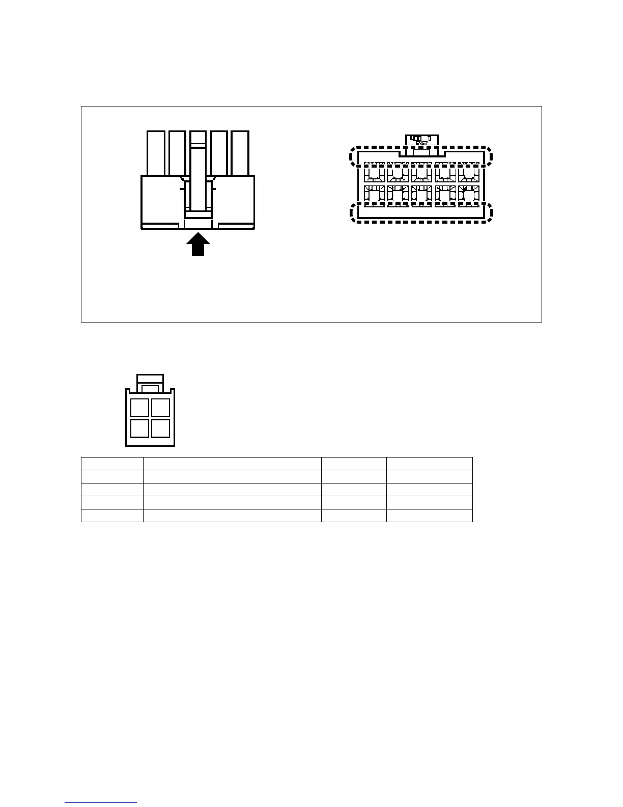
Identify the connector pin number as described below.
You may nd the numeric characters
indicated on the connector when
viewing from the direction of the arrow.
The numeric character
indicated on the connector,
as viewed from the direction
of the arrow, is the connector
pin number.
Connector
5 4 3 2 1
10 9 7 6
Pin No. Part name Color of cable Remarks
1 Alternate up/down limit switch (lower side) White
2 Alternate up/down limit switch (upper side) Red
3 Alternate up/down limit switch (lower side) Black GND
4 Alternate up/down limit switch (upper side) Green GND
* When connecting the connectors to the control box, prepare a junction cord using the below-stated connector pin ter-
minal.
Part number of the target connector : HK034620040 (MOLEX : 5559-04P)
Part number of the target pin terminal : HK034630000 (MOLEX : 5558TL)
①
CN158: 4P connector (alternate up/down switch)
2 1
4 3
 Loading...