Page 2
The device has the following default configuration set when you power it on for the first
time. You can use the device without performing any initial configuration.
Factory Default Settings:
Factory-Default Settings for Security Policies:
Factory-Default Settings for NAT Rules:
Task 1: Connect the Power Cable and a Power Source
Connect the power cable to the device and a power source. We recommend using a
surge protector. Note the following indications:
POWER LED (green): The device is receiving power.
STATUS LED (green): The device is operating normally.
ALARM LED (amber): The device is operating normally, although the LED might be
amber because a rescue configuration has not been set yet. This is not a panic
condition.
NOTE: After a rescue configuration has been set, an amber ALARM LED indicates a
minor alarm, and a solid red ALARM LED indicates a major problem on the services
gateway.
NOTE: You must allow the device between five and seven minutes to boot up after you
power it on. Wait until the STATUS LED is solid green before proceeding to the next task.
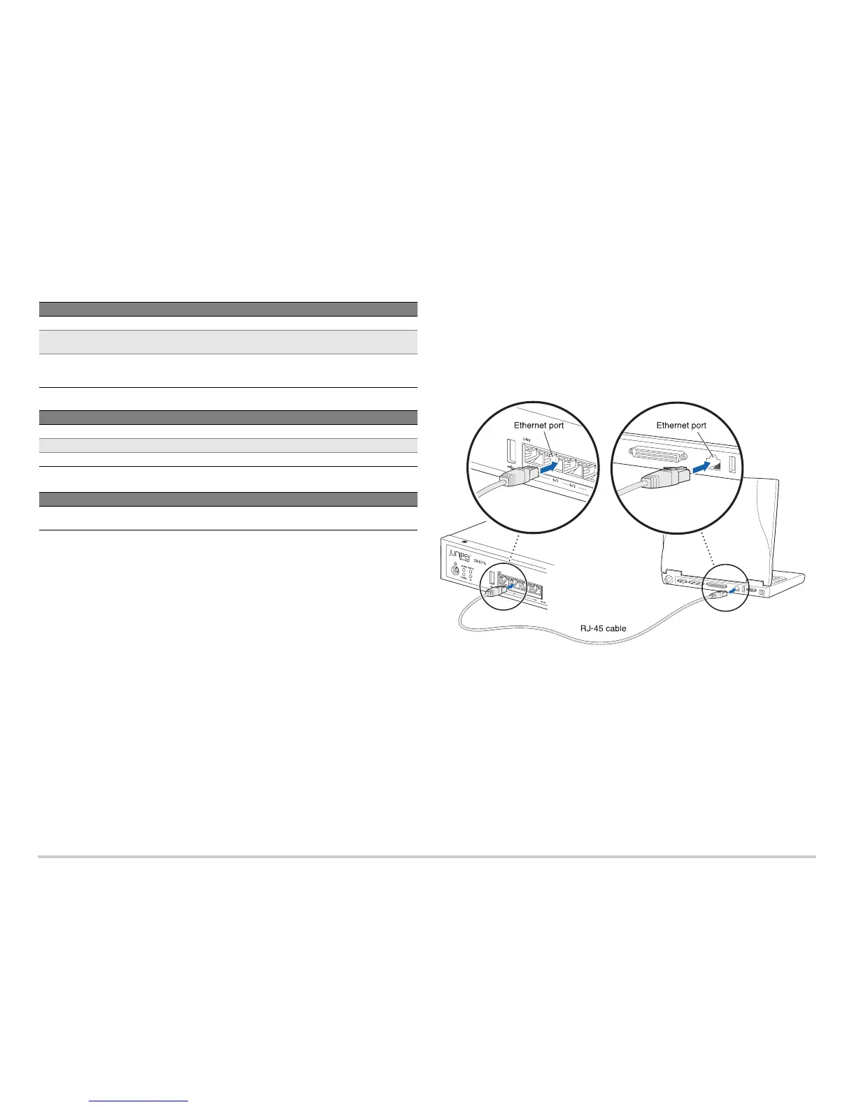
Task 2: Connect the Management Device
Connect the management device to the services gateway using either of the following
methods:
Connect an Ethernet cable from any one port between the ports labeled 0/1 and 0/7
(interfaces fe-0/0/1 through fe-0/0/7) on the front panel to the Ethernet port on the
management device (workstation or laptop).
We recommend this connection method. If you are using this method to connect,
proceed with Task 3.
Connect an Ethernet cable from the port labeled CONSOLE on the front panel to the
supplied DB-9 adapter, which then connects to the serial port on the management
device (Serial port settings: 9600 8-N-1-N).
If you are using this method to connect, proceed with the CLI configuration
instructions available in the Getting Started Guide for the Branch SRX Series at
http://www.juniper.net/techpubs/en_US/junos12.1x46/information-products
/topic-collections/security/software-all/getting-started-guide/
security-getting-started-guide.pdf.
See the following illustration for details on connecting a management interface.
Task 3: Ensure That the Management Device Acquires an IP Address
After you connect the management device to the services gateway, the DHCP server
process on the services gateway will automatically assign an IP address to the
management device. Ensure that the management device acquires an IP address on the
192.168.1.0/24 subnetwork (other than 192.168.1.1).
NOTE: If an IP address is not assigned to the management device, manually configure
an IP address in the 192.168.1.0/24 subnetwork. Do not assign 192.168.1.1 as the IP
address to the management device, as this IP address is assigned to the services
gateway. By default, the DHCP server is enabled on the Layer 3 VLAN interface, (IRB)
vlan.0 (fe-0/0/1 to fe-0/0/7), which is configured with the IP address 192.168.1.1/24.
When an SRX110 Services Gateway is powered on for the first time, it boots using
the factory default configuration.
Port Label Interface Security Zones DHCP State IP Address
0/0 fe-0/0/0 untrust client unassigned
0/1 to 0/7 fe-0/0/1 to
fe-0/0/7
trust server 192.168.1.1/24
VDSL/ADSL-POTS
or
VDSL/ADSL-ISDN
pt-1/0/0 untrust client unassigned
Source Zone Destination Zone Policy Action
trust untrust permit
trust trust permit
untrust trust deny
Source Zone Destination Zone Policy Action
trust untrust source NAT to untrust zone
interface
 Loading...