Page 2
Task 1: Connect the Power Cable to the Device
Connect the power supply adapter to the power supply point on the device and to a
power source. We recommend using a surge protector. Secure the connector to the
power supply point by wrapping a cable tie around the cable boot and the adjacent cable
tie holder. Note the following indications:
POWER LED (green): The device is receiving power.
STATUS LED (green): The device is operating normally.
ALARM LED (amber): The device is operating normally, but the LED might glow
amber if a rescue configuration has not been set. This is not a panic condition.
MPIM-1 and MPIM-2 LEDs (off): The Mini-Physical Interface Modules (Mini-PIMs)
are not present or are not detected by the device. If these LEDs are solid green, it
indicates that the Mini-PIMs are functioning normally.
NOTE: After a rescue configuration has been set, an amber Alarm LED indicates a minor
alarm, and a solid red Alarm LED indicates that a major problem exists on the services
gateway.
NOTE: You must allow the device between five and seven minutes to boot up after you
have powered it on. Wait until the Status LED is solid green before proceeding to the
next task.
Task 2: Connect the Management Device
Connect the management device to the services gateway using either of the following
methods:
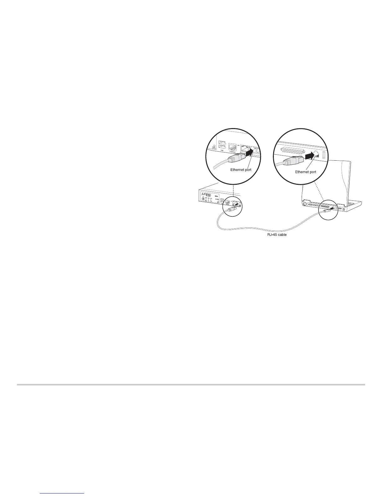
Connect an RJ-45 cable (Ethernet cable) from any of the ports labeled 0/1 through
0/7 (interfaces ge-0/0/1 through ge-0/0/7) on the front panel to the Ethernet port on
the management device (workstation or laptop).
We recommend this connection method. If you are using this method to connect,
proceed to Task 3.
Connect an RJ-45 cable (Ethernet cable) from the port labeled CONSOLE to the
supplied DB-9 adapter, which then connects to the serial port on the management
device. (Serial port settings: 9600 8-N-1.)
NOTE: If you are using this method to connect, proceed with the CLI configuration
instructions available in the Branch SRX Series Services Gateways Golden
Configurations at http://www.juniper.net/us/en/local/pdf/app-notes/3500153-en.pdf.
See the following illustration for details about connecting the management interface by
using the Ethernet ports.
Task 3: Ensure That the Management Device Acquires an IP Address
After you connect the management device to the services gateway, the DHCP server
process on the services gateway automatically assigns an IP address to the
management device. Ensure that the management device acquires an IP address on the
192.168.1.0/24 subnetwork (other than 192.168.1.1) from the services gateway.
NOTE:
The services gateway functions as a DHCP server and will assign an IP address to
the management device.
If an IP address is not assigned to the management device, manually configure an
IP address in the 192.168.1.0/24 subnetwork. Do not assign the 192.168.1.1 IP
address to the management device, as this IP address is assigned to the device. By
default, the DHCP server is enabled on the L3 VLAN interface, (IRB) vlan.0
(interfaces ge-0/0/1 through ge-0/0/7), which is configured with an IP address of
192.168.1.1/24.
When an SRX220 Services Gateway is powered on for the first time, it boots using
the factory-default configuration.
Task 4: Access the J-Web Interface
1. Launch a Web browser from the management device.
NOTE: The wizard works best with Mozilla Firefox version 15.x or later.
2. Type http://192.168.1.1 in the URL address field. The Welcome page appears.
g034422
 Loading...