SRX550 Services Gateway Quick Start
The instructions in this quick start help you connect the SRX550 Services Gateway to
your network. For complete details on the SRX550 Services Gateway, see the SRX550
Services Gateway Hardware Guide at
http://www.juniper.net/techpubs/a074.html .
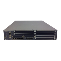
SRX550 Services Gateway Front Panel
NOTE: The AUX port is not functional on the SRX550 Services Gateway.
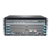
SRX550 Services Gateway Back Panel
NOTE: The ACE slot is not functional on the SRX550 Services Gateway.
Connecting and Configuring the SRX Series Services Gateways
Following are the tasks for connecting and configuring the SRX550 Services Gateway.
The LEDs on the front and back panels of the device indicate the status of the device.
NOTE: The device takes two minutes to boot up after you have powered it on. Wait until
the STATUS LED is solid green before proceeding to Task 3: Connect the Management
Device.
Task 1: Overview
The SRX550 Services Gateway requires these basic configuration settings to function:
Interfaces must be assigned IP addresses.
Interfaces must be bound to zones.
All interfaces must be configured as Layer 3 interfaces.
Policies must be configured between zones to permit or deny traffic.
Source Network Address Translation (NAT) rules must be set.
The device has the following default configuration set when you power it on for the first
time. To be able to use the device, you do not need to perform any initial configuration.
NOTE: Ports 0/6 to 0/9 are not configured by default.
Callout Description Callout Description
1 LEDs: ALARM, STATUS,
POWER, HA, MPIM-1,
MPIM-2, RPS, ACE, and
STORAGE
8 Reset Config button
2 Serial console port 9 Six fixed Gigabit Ethernet ports (0/0 - 0/5)
3 USB console port 10 Four SFP Ethernet ports (0/6 - 0/9)
4 AUX port 11 Two Mini-PIM slots numbered 1 and 2
5 ESD outlet 12 Six GPIM slots numbered 3 through 8.
Slot 3 supports 10-gigabit XPIMs and slot 6
supports 20-gigabit XPIMs.
6 USB 0 and USB 1 ports 13 Mounting bracket
7 Power button
Callout Description Callout Description
1 Power supply slots with LEDs: DC
OK and AC OK
4 Storage slot
2 ACE slot 5 ESD outlet
3 Grounding point 6 Air filter cover