(No.YF005)1-7
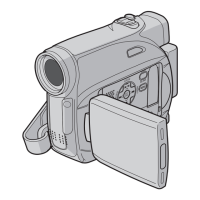
3.2.2 ASSEMBLY/DISASSEMBLY OF CABINET PARTS AND ELECTRICAL PARTS
zDisassembly procedure
NOTE4:
Be careful not to cut the FPC.
NOTE6:
Be careful about the engagement of the wire.
NOTE7:
Be careful not to cut the FPC.
Be careful about the engagement of the wire.
NOTE8:
Be careful not to cut the FPC.
Be careful about the engagement of the wire.
NOTE9:
For the disassembly procedure of the OP BLOCK ASSEM-
BLY, see "3.2.4 ASSEMBLY/DISASSEMBLY OF [9] OP
BLOCK ASSMBLY/CCD BOARD ASSEMBLY"
NOTE10:
Be careful not to cut the FPC.
NOTE11:
When removing/attaching the SHIELD COVER, be careful
not to damage the FPC.
NOTE12:
When removing/attaching the BRACKET (MECHA) AS-
SEMBLY, be careful not to damage the FPC.
For the disassembly/assembly procedure of the MECHA-
NISM ASSEMBLY, see the Service Manual "DVC MECHA-
NISM (No.86700)."
NOTE13a:
Remove the SHEET and the screw if necessary.
NOTE13b:
For the disassembly/assembly procedure of the VF ASSEM-
BLY, see "3.2.5 DISASSEMBLY/ASSEMBLY OF [13] VF
ASSEMBLY"
NOTE15a:
Be careful not to cut the FPC.
NOTE15b:
For the disassembly/assembly procedure of the MONITOR
ASSEMBLY, see "3.2.3 DISASSEMBLY/ASSEMBLY OF
[15] MONITOR ASSEMBLY"
NOTE16a:
Wires for the SPEAKER are soldered, and the BRACK-
ET(SPK) fixes the SPEAKER. Therefore, prior to removing
the MONI-C BOARD ASSEMBLY, unsolder the soldered
points (SD16) so that the wires moves easily.
NOTE16b:
When attaching the MONI-C BOARD ASSEMBLY, be care-
ful of the position of the KNOB(SLIDE) and the SWITCH of
the BOARD.
NOTE17:
Be careful about the engagement of the wire.
zDestination of connectors
STEP
No.
PART NAME
Fig.
No.
POINT NOTE
[1]
[2]
[3]
[4]
[5]
[6]
[7]
[8]
[9]
[10]
[11]
/[12]
[13]
[14]
[15]
[16]
[17]
ORNAMENT(TOP)
COVER(JIG)
COVER(UPPER)
UPPER CASE ASSY
(INCLUDE VF(COLOR)ASSY, MONITOR ASSY)
COVER(ZOOM)
FRONT COVER ASSY
REAR UNIT ASSY
LOWER CASE ASSY
OP BLOCK ASSY
MAIN BOARD ASSY
PREMDA BOARD ASSY
/MECHANISM ASSY
VF ASSY
COVER(HINGE)
MONITOR ASSY
MONI-C BOARD ASSY
SPEAKER
2(L1)
(S2)
(S3a),(S3b),2(L3)
2(S4a),3(S4b),(S4c),(S4d),(S4a),
CN4a,CN4b
2(S5),(L5)
(S6),2(L6a),(L6b)
CN7a,CN7b,(S7),(L7a),(L7b)
CN8a,CN8b,CN8c,6(S8),4(L8)
CN9a,CN9b,2(S9),(L9a),(L9b)
(S10a),(S10b),2(L10),CN10a,CN10b
2(S11a),L11,CN11a,b,c,d,e,f,2(S11b)
3(S12),BKT(MECHA)ASSY
CN13,(S13a),(S13b),(L13)
(S14a),2(S14b)
2(S15a),CN15,2(S15b)
SD16,2(S16a),2(S16b),2(L16),
KNOB(SLIDE)
2(S17a),(S17b),BKT(HINGE),
2(S17a),BKT(SPK)
Fig.C1
Fig.C2
Fig.C3
Fig.C4
Fig.C5
Fig.C6
Fig.C7
Fig.C8
Fig.C9
Fig.C10
Fig.C11
Fig.C12
Fig.C13
-
-
-
NOTE4
-
NOTE6
NOTE7
NOTE8
NOTE9
NOTE10
NOTE11
NOTE12
NOTE13a,b
-
NOTE15a,b
NOTE16a,b
NOTE17
CN.NO.
CONNECTOR
PIN
NO.
CN4a MAIN CN101 MONI-C CN7614 40
CN4b MAIN CN103 MONI-C CN762 10
CN7a MAIN CN104
REAR UNIT ASSY
CN408 8
CN7b MAIN CN112
REAR UNIT ASSY
CN401 12
CN8a MAIN CN102 FRONT CN9001 6
CN8b MAIN CN106 MIC - 4
CN8c MAIN CN109 ZOOM UNIT - 16
CN9a MAIN CN108 OP BLOCK ASSY - 24
CN9b MAIN CN107 CCD CN5001 16
CN10a MAIN CN110 PREMDA CN408 40
CN10b MAIN CN111 PREMDA CN401 40
CN11a PREMDA CN406 SENSOR - 16
CN11b PREMDA CN405 CAPSTAN MOTOR - 18
CN11c PREMDA CN404 DRUM MOTOR CN901 11
CN11d PREMDA CN402 HEAD - 8
CN11e PREMDA CN403 LOADING MOTOR - 6
CN11f PREMDA CN407 ROTARY ENCODER - 6
CN13 MONI-C CN765 MONITOR ASSY - 32
CN15 MONI-C CN763 VF ASSY CN7001 18
 Loading...