(No.MA111)1-7
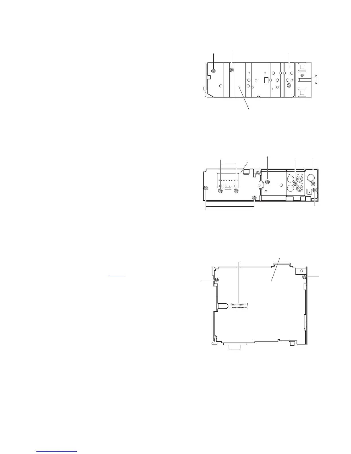
3.1.4 Removing the side panel
(See Fig.4)
• Prior to performing the following procedure, remove the front
panel assembly as required.
(1) Remove the screw B and two screws C attaching the side
panel on the left side of the main body, and remove the side
panel.
Fig.4
3.1.5 Removing the rear bracket
(See Fig.5)
• Prior to performing the following procedure, remove the bottom
cover.
(1) Remove the three screws D, three screws E and two
screws F attaching the rear bracket on the back side of the
main body.
(2) Remove the rear bracket.
Fig.5
3.1.6 Removing the main board
(See Fig.6)
• Prior to performing the following procedure, remove the front
panel assembly, front chassis assembly, side panel, bottom
cover and rear bracket.
(1) Remove the two screws G attaching the main board.
(2) Disconnect the connector CN501
and remove the main
board.
Fig.6
Side panel
BCC
EF
D
D
E
Rear bracket
F
Main board
G
G
CN501
 Loading...