1-8 (No.MA134)
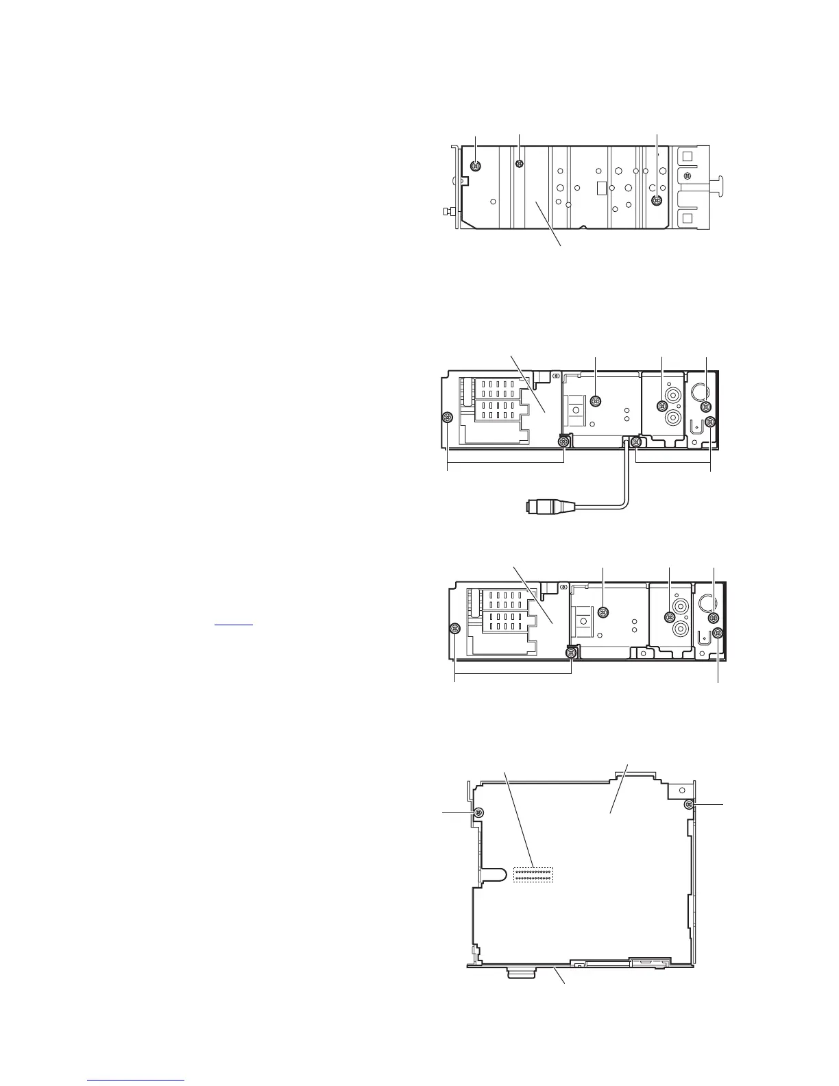
3.1.4 Removing the side panel
(See Fig.4)
Reference:
Remove the front panel assembly as required.
(1) Remove the screw B and two screws C attaching the side
panel on the left side of the main body.
(2) Remove the side panel from the main body.
Fig.4
3.1.5 Removing the rear bracket
(See Fig.5)
• Remove the bottom cover.
(1) For KD-G311 and KD-G312, remove the four screws D,
one screw E and two screws F attaching the rear bracket
on the back side of the main body.
(2) For KD-G317, remove the three screws D, one screw E
and two screws F attaching the rear bracket on the back
side of the main body.
(3) Remove the rear bracket.
3.1.6 Removing the main board
(See Figs.5 and6)
• Remove the front panel assembly, bottom cover and side pan-
el.
Reference:
Remove the front chassis assembly as required.
(1) Remove the three screws D attaching the rear bracket on
the back side of the main body. (See Fig.5.)
(2) Remove the two screws G attaching the main board. (See
Fig.6.)
(3) Disconnect the connector CN501
on the main board from
the main body and take out the main board with the rear
bracket. (See Fig.6.)
Reference:
Remove the rear bracket from the main body as required. (See
"3.1.5 Removing the rear bracket".)
Fig.5
Fig.6
Side panel
C
B
C
D
D
E
Rear bracket
FF
(KD-G311,KD-312)
(KD-G317)
D
D
E
Rear bracket
FF
Main board
G
G
CN501
Rear bracket
 Loading...