(No.MA074)1-7
3.1.4 Removing the side panel
(See Fig.5)
• Prior to performing the following procedure, remove the front
panel assembly as required.
(1) From the left side of the main body, remove the two screws
C and screw D attaching the side panel.
Fig.5
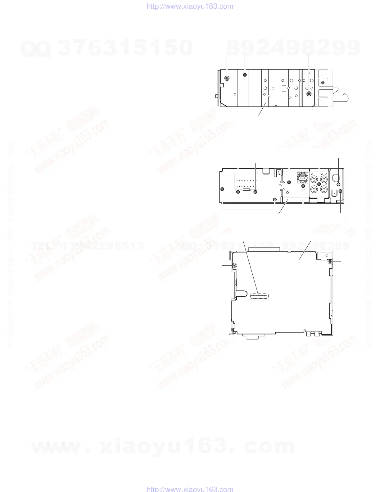
3.1.5 Removing the rear bracket
(See Fig.6)
• Prior to performing the following procedure, remove the bottom
cover.
(1) From back side of the main body, remove the three screws
E, three screws F and three screws G attaching the rear
bracket.
(2) Remove the rear bracket.
3.1.6 Removing the main board
(See Figs.6 and 7)
• Prior to performing the following procedures, remove the front
panel assembly, bottom cover, front chassis assembly and
side panel.
• Remove the front chassis assembly as required.
(1) Remove the three screws E attaching the rear bracket on
the back side of the main body. (See fig.6.)
(2) From the bottom side of the main body, remove the two
screws H attaching the main board. (See fig.7.)
(3) Disconnect the connector CN501 from the CD mechanism
assembly and remove the main board. (See fig.7.)
Reference:
Remove the rear bracket from the main body as re-
quired.(SeeÅh2.1.5 Removing the rear bracketÅh.)
Fig.6
Fig.7
Side panel
CCD
G
E
G
Rear bracket
G
F
E
F
Main board
H
H
CN501
w
w
w
.
x
i
a
o
y
u
1
6
3
.
c
o
m
Q
Q
3
7
6
3
1
5
1
5
0
9
9
2
8
9
4
2
9
8
T
E
L
1
3
9
4
2
2
9
6
5
1
3
9
9
2
8
9
4
2
9
8
0
5
1
5
1
3
6
7
3
Q
Q
TEL 13942296513 QQ 376315150 892498299
TEL 13942296513 QQ 376315150 892498299
http://www.xiaoyu163.com
http://www.xiaoyu163.com
 Loading...