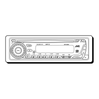
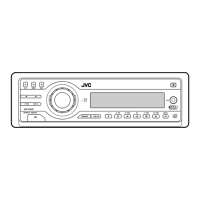
KD-G401
Installation/Connection Manual
Einbau/Anschlußanleitung
Manuel d’installation/raccordement
Handleiding voor installatie/aansluiting
1103KKSMDTJEIN
EN, GE, FR, NL
GET0195-005A
[E/EX]
J
Handles
Griffe
Poignées
Hendels
F
Washer (ø5)
Unterlegscheibe (ø5)
Rondelle (ø5)
Sluitring (ø5)
G
Lock nut (M5)
Sicherungsmutter (M5)
Ecrou d’arrêt (M5)
Contra-moer (M5)
H
Mounting bolt (M5 x 20 mm)
Befestigungsschraube (M5 x 20 mm)
Boulon de montage (M5 x 20 mm)
Bevestigingsbout (M5 x 20 mm)
I
Rubber cushion
Gummipuffer
Amortisseur en caoutchouc
Rubberdop
Teileliste für den Einbau und Anschluß
Die folgenden Teile werden zusammen mit
diesem Gerät geliefert.
Nach ihrer Überprüfung, die Teile richtig einsetzen.
Liste des pièces pour l’installation et
raccordement
Les pièces suivantes sont fournies avec cet
appareil.
Après vérification, veuillez les placer correctement.
Lijst van onderdelen die u bij
installatie en aansluiting nodig hebt
De volgende onderdelen worden bij het apparaat
geleverd.
Installeer ze op de juiste wijze, nadat u ze hebt
gecontroleerd.
Parts list for installation and
connection
The following parts are provided for this unit.
After checking them, please set them correctly.
A / B
Hard case/Control panel
Etui/Schalttafel
Etui de transport/Panneau de
commande
Behuizing/Bedieningspaneel
C
Sleeve
Halterung
Manchon
Huis
D
Trim plate
Frontrahmen
Plaque d’assemblage
Sierplaat
E
Power cord
Stromkable
Cordon d’alimentation
Stroomkabel
INSTALLATIE (INBOUW IN
HET DASHBOARD)
Op de volgende afbeelding kunt u zien hoe de
installatie, normaal gesproken, in zijn werk gaat.
Neem bij vragen of voor meer bijzonderheden over
inbouwpakketten contact op met uw JVC car audio
dealer of een dealer of een bedrijf dat
inbouwpakketten levert.
• Als u niet zeker weet hoe u dit apparaat moet
installeren, kunt u dit beter door een daartoe
gekwalificeerde technicus laten doen.
INSTALLATION (MONTAGE
DANS LE TABLEAU DE BORD)
L’illustration suivante est un exemple
d’installation typique. Si vous avez des
questions ou avez besoin d’information sur des
kits d’installation, consulter votre revendeur
d’autoradios JVC ou une compagnie
d’approvisionnement.
•
Si l’on n’est pas sûr de pouvoir installer
correctement cet appareil, le faire installer par
un technicien qualifié.
EINBAU
(IM ARMATURENBRETT)
Die folgende Abbildung zeigt einen typischen
Einbau. Bei irgendwelchen Fragen oder wenn
Sie Informationen hinsichtlich des Einbausatzes
brauchen, wenden Sie sich an ihren JVC
Autoradiohändler oder ein Unternehmen das
diese Einbausätze vertreibt.
• Sind Sie sich über den richtigen Einbau des
Geräts nicht sicher, lassen Sie es von einem
qualifizierten Techniker einbauen.
INSTALLATION
(IN-DASH MOUNTING)
The following illustration shows a typical
installation. If you have any questions or require
information regarding installation kits, consult
your JVC IN-CAR ENTERTAINMENT dealer or
a company supplying kits.
• If you are not sure how to install this unit
correctly, have it installed by a qualified
technician.
*
1
When you stand the unit, be careful
not to damage the fuse on the rear.
*
1
Beim Aufstellen des Geräts darauf
achten, daß die Sicherung auf der
Rückseite nicht beschädigt wird.
*
1
Lorsque vous mettez l’appareil à la
verticale, faire attention de ne pas
endommager le fusible situé sur
l’arrière.
*
1
Wanneer u het apparaat rechtop zet,
moet u erop letten dat u de zekering
aan de achterkant niet beschadigt.
B
D
C
J
B
D
C
H
*1
Do the required electrical connections.
Nehmen Sie die erforderlichen
elektrischen Anschlüsse vor.
Réalisez les connexions électriques.
Breng de vereiste elektrische verbindingen
tot stand.
Bend the appropriate tabs to hold the
sleeve firmly in place.
Die geeigneten Zapfen biegen, um
die Manschette sicher festzuhalten.
Tordez les languettes appropriées
pour maintenir le manchon en place.
Buig de vereiste lipjes zodat de huls goed
op zijn plaats wordt gehouden.
1
NEDERLANDS
Dit apparaat mag worden gebruikt bij elektrische
systemen die werken op 12 V gelijkstroom met
negatieve aarding. Als uw auto niet is uitgerust
met een dergelijk systeem, is een spanningsomzetter
vereist. Dit instrument kan worden aangeschaft bij
JVC car audio dealers.
FRANÇAIS
Cet appareil est conçu pour fonctionner sur des
sources de courant continu de
12 V à masse
NEGATIVE
. Si votre véhicule n’offre pas ce type
d’alimentation, il vous faut un convertisseur de
tension, que vous pouvez acheter chez un
revendeur d’autoradios JVC.
DEUTSCH
Dieses Gerät ist für einen Betrieb in
elektrischen Anlagen mit 12 V Gleichstrom
und (–) Erdung ausgelegt. Verfügt Ihr
Fahrzeug nicht über diese Anlage, ist ein
Spannungsinverter erforderlich, der bei JVC
Autoradiohändler erworben werden kann.
ENGLISH
This unit is designed to operate on 12 V DC,
NEGATIVE ground electrical systems. If your
vehicle does not have this system, a voltage
inverter is required, which can be purchased at
JVC IN-CAR ENTERTAINMENT dealers.
I
Instal1-2_KD-G401_005A_f.p65 7/11/03, 6:41 PM1